Admin
مدير المنتدى


عدد المساهمات : 18864
التقييم : 35108
تاريخ التسجيل : 01/07/2009
الدولة : مصر
العمل : مدير منتدى هندسة الإنتاج والتصميم الميكانيكى
 |  موضوع: تجميعه رموز الدوائر الهيدروليكية - Pooyan Hydraulics - Basic Symbols الخميس 26 مايو 2022, 6:39 pm موضوع: تجميعه رموز الدوائر الهيدروليكية - Pooyan Hydraulics - Basic Symbols الخميس 26 مايو 2022, 6:39 pm | |
| 
أخواني في الله
أحضرت لكم كتاب
و المحتوى كما يلي :
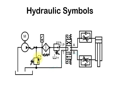
تجميعه رموز الدوائر الهيدروليكية
Pooyan Hydraulics - Basic Symbols
2) L= Length of dash, E = Thickness of line, D = Space between lines
DESCRIPTION SYMBOL APPLICATION
BASIC SYMBOLS
Line
- continuous
- long dashes
- short dashes
- double
- long chain thin
(optional use)
Circle, semi-circle
mechanical connections (shafts, levers, pistonrods)
Enclosure for several components assembled
in one unit
As a rule, energy conversion units (pump,
compressor, motor)
Measuring instruments
Non-return link, roller, etc
Mechanical link, roller, etc.
Semi-rotary actuator
E } flow lines
DESCRIPTION SYMBOL APPLICATION
d d ≈ 5E
Square, rectangle
Diamond
Miscellaneous
symbols
Triangle:
- solid
- in outline only
Arrow
Sloping arrow
FUNCTIONAL
SYMBOLS
As a rule, control valves (valve) except for nonreturn valves
Conditioning apparatus (filter, separator,
lubricator, heat exchanger)
Flow line connection
Spring
Restriction:
- affected by viscosity
- unaffected by viscosity
The direction of flow and the nature of the fluid
Hydraulic flow
Pneumatic flow or exhaust to atmosphere
Indication of:
- direction
- direction of rotation
- path and direction of flow through valves.
For regulating apparatus as in 3.4 both
representations, with or without a tail to the
end of the arrow, are used without distinction
As a general rule the line perpendicular to the
head of the arrow indicates that when the
arrow moves, the interior path always remains
connected to the corresponding exterior path
Indication of the possibility of a regulation or a
progressive variabilityI S O F L U I D P O W E R G R A P H I C S Y M B O L S
DESCRIPTION SYMBOL USE OF THE EQUIPMENT
OR EXPLANATION OF THE SYMBOL
OUTLET
INLET
BALL CHECK
U
PUMPS AND
COMPRESSORS
Fixed capacity
hydraulic pump:
- with one
direction of flow
- with two
directions of flow
Variable displacement
hydraulic pump:
- with one
direction of flow
- with two
directions of flow
Fixed capacity
compressor (always
one direction of flow)
To convert mechanical
energy into hydraulic or
pneumatic energy.
The symbol is a
combination of 2.1.1.1
and 1.2.3 (sloping
arrow)
The symbol is a
combination of 2.1.1.2
and 1.2.3 (sloping
arrow)I S O F L U I D P O W E R G R A P H I C S Y M B O L S
DESCRIPTION SYMBOL
SPRING
To convert hydraulic or
pneumatic energy into rotary
mechanical energy
The symbol is a combination of
2.2.1.1 and 1.2.3 (sloping arrow)
The symbol is a combination of
2.2.1.2 and 1.2.3 (sloping arrow)
The symbol is a combination of
2.2.3.1 and 1.2.3 (sloping arrow)
The symbol is a combination of
2.2.3.2 and 1.2.3 (sloping arrow)
MOTORS
Fixed capacity
hydraulic motor:
- with one
direction of flow
- with two
directions of flow
Variable displacement
hydraulic motor:
- with one
direction of flow
- with two
directions of flow
Fixed displacement
pneumatic motor:
- with one
direction of flow
- with two
directions of flow
Variable displacement
hydraulic motor:
- with one
direction of flow
- with two
directions of flow
Oscillating motor:
- hydraulic
- pneumatic
USE OF THE EQUIPMENT
OR EXPLANATION OF THE SYMBOLI S O F L U I D P O W E R G R A P H I C S Y M B O L S
DESCRIPTION SYMBOL
PUMP/MOTOR UNITS
Fixed displacement
pump/motor unit:
- with reversal of the
direction of flow
- with one single
direction of flow
- with two directions
of flow
Variable displacement
pump/motor unit:
- with reversal of the
direction of flow
- with one single
direction of flow
- with two directions
of flow
VARIABLE SPEED DRIVE
UNITS
CYLINDERS
Single acting cylinder:
- returned by an
unspecified force
- returned by spring
USE OF THE EQUIPMENT
OR EXPLANATION OF THE SYMBOL
Unit with two functions,
either as pump or as rotary
motor
Functioning as pump or
motor according to direction
of flow
Functioning as pump or
motor without change of
direction of flow
Functioning as pump or
motor with either direction of
flow
The symbol is a combination
of 2.3.1.1 and 1.2.3 (sloping
arrow)
The symbol is a combination
of 2.3.1.2 and 1.2.3 (sloping
arrow)
The symbol is a combination
of 2.3.1.3 and 1.2.3 (sloping
arrow)
Torque converter. Pump
and/or motor are variable
capacity. Remote drives, see
8.2
Equipment to convert
hydraulic or pneumatic
energy into linear energy
Cylinder in which the fluid
pressure always acts in one
and the same direction (on
the extension stroke)
General symbol when the
method of return is not
specified
Combination of the general
symbols 2.5.1.1 and 1.1.5.2
(spring)
Detailed SimplifiedI S O F L U I D P O W E R G R A P H I C S Y M B O L S
DESCRIPTION SYMBOL
Double acting cylinder:
- with single piston
rod
- with double-ended
piston rod
Differential cylinder
Cylinder with cushion:
- with single fixed
cushion
- with double fixed
cushion
- with single
adjustable cushion
- with double
adjustable cushion
Telescopic cylinder:
- single acting
- double acting
USE OF THE EQUIPMENT
OR EXPLANATION OF THE SYMBOL
Cylinder in which pressure
fluid operates alternately in
both directions (extend and
retract strokes)
The action is dependent on
the difference between the
effective areas on each side
of the piston
Cylinder incorporating fixed
cushion acting in one
direction only
Cylinder with fixed cushion
acting in both directions
The symbol is a
combination of 2.5.4.1 and
1.2.3 (sloping arrow)
The symbol is combination
of 2.5.4.2 and 1.2.3
(sloping arrow)
The fluid pressure always
acts in one and the same
direction (on the extend
stroke)
The fluid pressure operates
alternately in both
directions (extend and
retract strokes)I S O F L U I D P O W E R G R A P H I C S Y M B O L S
DESCRIPTION SYMBOL
PRESSURE
INTENSIFIERS:
- for one type of fluid
- for two types of
fluid
AIR-OIL ACTUATOR
METHOD OF
REPRESENTATION OF
VALVES (EXCEPT 7.3
AND 7.6)
One single square
Two or more squares
USE OF THE EQUIPMENT
OR EXPLANATION OF THE SYMBOL
CONTROL
VALVES
Detailed Simplified
Equipment transforming a
pressure x into a higher
pressure y
E.g. a pneumatic pressure x is
transformed into a higher
pneumatic pressure y
E.g. a pneumatic pressure x is
transformed into a higher
hydraulic pressure y
Equipment transforming a
pneumatic pressure into a
substantially equal hydraulic
pressure or vice versa
Made up of one or more
squares 1.1.3 and arrows
In circuit diagrams hydraulic
and pneumatic units are
normally shown in the
unoperated condition
Indicates unit for controlling
flow or pressure, having in
operation and infinite number
of possible positions between
its end positions so as to vary
the conditions of flow across
one or more of its ports, thus
ensuring the chosen pressure
and/or flow with regard to the
operating conditions of the
circuit
Indicate a directional control
valve having as many distinct
positions as there are
squares. The pipe
connections are normally
represented as representing
the unoperated condition (see
3.1). The operating positions
are deduced by imagining the
boxes to be displaced so that
the pipe connections
correspond with the ports of
the box in questionI S O F L U I D P O W E R G R A P H I C S Y M B O L S
DESCRIPTION SYMBOL
Simplified symbol for
valves in cases of
multiple repetition
DIRECTIONAL
CONTROL VALVES
Flow paths:
- one flow path
- two closed ports
- two flow paths
- two flow paths
and one closed port
- two flow paths
with cross connection
- one flow path in a
bypass position, two
closed ports
Non-throttling
directional control
valve
USE OF THE EQUIPMENT
OR EXPLANATION OF THE SYMBOL
3 The number refers to a note
on the diagram in which the
symbol for the valve is given
in full
Units providing for the
opening (fully or restricted)
or the closing of one or
more paths (represented by
several squares)
Square containing interior
lines
The unit provides distinct
circuit conditions each
depicted by a square
Basic symbol for 2-position
directional control valve
Basic symbol for 3-position
directional control valve
A transitory but significant
condition between two
distinct positions is
optionally represented by a
square with dashed endsI S O F L U I D P O W E R G R A P H I C S Y M B O L S
DESCRIPTION SYMBOL
Designation: The first
figure in the
designation shows the
number of ports
(excluding pilot ports)
and the second figure
the number of distinct
positions
Directional control
valve 2/2:
- with manual control
- controlled by
pressure operating
against a spring (e.g.,
on air unloading valve)
Directional control valve
3/2:
- controlled by
pressure in both
directions
- controlled by
solenoid with return
spring
Directional control
valve 4/2:
- controlled by
pressure in both
directions by means of
pilot valve (with single
solenoid and spring
return)
Directional control
valve 5/2:
- controlled by
pressure in both
directions
USE OF THE EQUIPMENT
OR EXPLANATION OF THE SYMBOL
Detailed
Simplified
Directional control valve
with 2 ports and 2 distinct
positions
Directional control valve
with 3 ports and 2 distinct
positions
Indicating an intermediate
condition (see 3.2.2.3)
Directional control valve
with 4 ports and 2 distinct
positions
Directional control valve
with 5 ports and 2 distinct
positionsI S O F L U I D P O W E R G R A P H I C S Y M B O L S
DESCRIPTION SYMBOL
Throttling directional
control
- with 2 ports (one
throttling orifice)
- with 3 ports (two
throttling orifices)
- with 4 ports (four
throttling orifices)
Electro-hydraulic
servo valve:
Electro-pneumatic
servo valve:
- single-stage
- two-stage with
mechanical feedback
- two-stage with
hydraulic feedback
USE OF THE EQUIPMENT
OR EXPLANATION OF THE SYMBOL
T B P A T
Torque motor
armature
Torque motor
Spool
The unit has 2 extreme
positions and an infinite
number of intermediate
conditions with varying
degrees of throttling
All the symbols have
parallel lines along the
length of the boxes. For
valves with mechanical
feedback see 5.3
Showing the extreme
positions
Showing the extreme
positions and a central
(neutral) position
For example: Tracer valve
plunger operated against a
return spring
For example: Directional
control valve controlled by
pressure against a return
spring
For example: Tracer valve,
plunger operated against a
return spring
A unit which accepts an
analog electrical signal and
provides a similar analog
fluid power output
- with direct operation
- with indirect pilot
operation
- with indirect pilot
operationI S O F L U I D P O W E R G R A P H I C S Y M B O L S
DESCRIPTION SYMBOL
NON-RETURN VALVES,
SHUTTLE VALVE,
RAPID EXHAUST
VALVE
Non-return valve
- free
- spring loaded
- pilot controlled
- a pilot signal
closes the valve
- a pilot signal
opens the valve
- with restriction
Shuttle valve
Rapid exhaust valve
PRESSURE CONTROL
VALVES
Pressure control valve:
- 1 throttling orifice
normally closed
USE OF THE EQUIPMENT
OR EXPLANATION OF THE SYMBOL
P
Outlet
Drain
Pilot
Valves which allow free flow
in one direction only
Opens if the inlet pressure is
higher than the outlet
pressure
Opens if the inlet pressure is
greater than the outlet
pressure plus the spring
pressure
As 3.3.1.1 but by pilot control
it is possible to prevent
Unit allowing free flow in one
direction but restricted flow
in the other
The inlet port connected to
the higher pressure is
automatically connected to
the outlet port while the other
inlet port is closed
When the inlet port is
unloaded the outlet port is
freely exhausted
Units ensuring the control of
pressure. Represented by one
single square as in 3.1.1 with
one arrow (the tail to the
arrow may be placed at the
end of the arrow). For interior
controlling conditions see
5.2.4.3
General symbolsI S O F L U I D P O W E R G R A P H I C S Y M B O L S
DESCRIPTION SYMBOL
- 1 throttling orifice
normally open
- 2 throttling
orifices, normally
closed
Pressure relief valve
(safety valve):
- with remote pilot
control
Proportional pressure
relief
Sequence valve
Pressure regulator or
reducing valve
(reducer of pressure):
- without relief port
- without relief port
with remote control
- with relief port
USE OF THE EQUIPMENT
OR EXPLANATION OF THE SYMBOL
System
T
P T
Outlet
P T
Outlet
Inlet pressure is controlled
by opening the exhaust port
to the reservoir or to
atmosphere against an
opposing force (for example
a spring)
The pressure at the inlet
port is limited as in 3.4.2 or
to that corresponding to the
setting of a pilot control
Inlet pressure is limited to a
value proportional to the
pilot pressure (see
5.2.4.1.3)
When the inlet pressure
overcomes the opposing
force of the spring, the valve
opens permitting flow from
the outlet port
A unit which, with a
pressure variable inlet
pressure, gives substantially
constant output pressure
provided that the inlet
pressure remains higher
than the required outlet
pressure
As in 3.4.5.1, but the outlet
pressure is dependent on
the control pressureDESCRIPTION SYMBOL
- with relief port,
with remote control
Differential pressure
regulator
Proportional pressure
regulator
FLOW CONTROL
VALVES
Throttle valve:
- with manual
control
- with mechanical
control against a
return spring (braking
valve)
Flow control valve:
- with fixed output
- with fixed output
and relief port to
reservoir
USE OF THE EQUIPMENT
OR EXPLANATION OF THE SYMBOL
I S O F L U I D P O W E R G R A P H I C S Y M B O L S
Detailed Simplified
Inlet Outlet
Inlet Outlet
Fixed orifice
Control orifice
As in 3.4.5.3, but the outlet
pressure is dependent on the
control pressure
The outlet pressure is
reduced by a fixed amount
with respect to the inlet
pressure
The outlet pressure is
reduced by a fixed ratio with
respect to the inlet pressure
(see 5.2.4.1.3)
Units ensuring control of
flow excepting 3.5.3
positions and method of
representation as 3.4
Simplified symbol (does not
indicate the control method
or the state of the valve)
Detailed symbol (indicates
the control method of the
state of the valve)
Variations in inlet pressure
do not affect the rate of flow
As 3.5.2.1 but with relief for
excess flow
1998/1999 Fluid Power Handbook & Directory A/239DESCRIPTION SYMBOL
- with variable
output
- with variable
output and relief port
to reservoir
Flow dividing valve
SHUT-OFF VALVE
SOURCES OF ENERGY
Pressure source
Hydraulic pressure
source
Pneumatic pressure
source
Electric motor
Heat engine
FLOW LINES AND
CONNECTIONS
Flow line:
- working line,
return line and feed
line
- pilot control line
USE OF THE EQUIPMENT
OR EXPLANATION OF THE SYMBOL
I S O F L U I D P O W E R G R A P H I C S Y M B O L S
M M
Control chamber
Vent connection
Inlet
Tank
Outlet
As 3.5.2.1 but with
arrow 5.2.3 added to the
symbol of restriction
As 3.5.2.3 but with relief
for excess flow
The flow is divided into
two flows in a fixed ratio
substantially
independent of pressure
variations
Simplified symbol
Simplified general
symbol
Symbols to be used
when the nature of the
source should be
indicated
Symbol 113 in IEC
Publication 117.2
A/240
ENERGY TRANSMISSION AND CONDITIONINGI S O F L U I D P O W E R G R A P H I C S Y M B O L S
DESCRIPTION SYMBOL
- drain or bleed line
- flexible pipe
- electric line
Pipeline junction
Crossed Pipelines
Air bleed
Exhaust port:
- plain with no
provision for
connection
- threaded for
connection
Power take-off:
- plugged
- with take-off line
Quick-acting coupling:
- connected, without
mechanically opened
non-return valve
- connected, with
mechanically opened
non-return valves
- uncoupled, with
open end
- uncoupled, closed
by free non-return
valve (see 3.3.1.1)
USE OF THE EQUIPMENT
OR EXPLANATION OF THE SYMBOL
Flexible hose, usually
connecting moving parts
not connected
On equipment or lines, for
energy take-off or measurementI S O F L U I D P O W E R G R A P H I C S Y M B O L S
DESCRIPTION SYMBOL
Rotary connection:
- one way
- three way
Silencer
RESERVOIRS
Reservoir open to
atmosphere:
- with inlet pipe
above fluid level
- with inlet pipe
below fluid level
- with a header line
Pressurized reservoir
ACCUMULATORS
FILTERS, WATER
TRAPS, LUBRICATORS
AND MISCELLANEOUS
APPARATUS
Filter or strainer
Water trap
USE OF THE EQUIPMENT
OR EXPLANATION OF THE SYMBOL
Air or gas
Bowl
Filer
element
Line junction allowing angular
movement in service
The fluid is maintained under
pressure by a spring, weight
or compressed gas (air,
nitrogen, etc.)I S O F L U I D P O W E R G R A P H I C S Y M B O L S
DESCRIPTION SYMBOL
- with manual
control drain
- automatically
drained
Filter with water trap:
- with manual
control
- automatically
drained
Air dryer
Lubricator
Conditioning unit
- Detailed symbol
- Simplified symbol
HEAT EXCHANGERS
USE OF THE EQUIPMENT
OR EXPLANATION OF THE SYMBOL
Float
Desiccant
Inlet air
Lubricated
air
Combination of 4.5.1 and
4.5.2.1
Combination of 4.5.1 and
4.5.2.2
A unit drying air (for
example, by chemical
means)
Small quantities of oil are
added to the air passing
through the unit, in order
to lubricate equipment
receiving the air
Consisting of filter,
pressure regulator,
pressure gage and
lubricator
Apparatus for heating or
cooling the circulating
fluidI S O F L U I D P O W E R G R A P H I C S Y M B O L S
DESCRIPTION SYMBOL
Temperature controller
Cooler
Heater
Mechanical
components
Rotating shaft:
- in one direction
- in either direction
Detent
Locking device
Over-center device
Pivoting devices:
- simple
USE OF THE EQUIPMENT
OR EXPLANATION OF THE SYMBOL
The fluid temperature is
maintained between two
predetermined values. The
arrows indicate that heat
may be either introduced or
dissipated
The arrows in the diamond
indicate the extraction of heat
- without representation of
the flow lines of the coolant
- indicating the flow lines
of the coolant
The arrows in the diamond
indicate the introduction of
heat
The arrow indicates rotation
A device for maintaining a
given position
* The symbol for unlocking
control is inserted in the
square
Prevents the mechanism
from stopping in a dead
center position
CONTROL MECHANISMSI S O F L U I D P O W E R G R A P H I C S Y M B O L S
DESCRIPTION SYMBOL
- with traversing
lever
- with fixed fulcrum
CONTROL METHODS
Muscular control:
- by pushbutton
- by lever
- by pedal
Mechanical control:
- by plunger or
tracer
- by spring
- by roller
- by roller, operating
in one direction only
Electrical control:
- by solenoid
USE OF THE EQUIPMENT
OR EXPLANATION OF THE SYMBOL
The symbols representing control
methods are incorporated in the
symbol of the controlled
apparatus, to which they should be
adjacent. For apparatus with
several squares the actuation of
the control makes effective the
square adjacent to it.
General symbol (without indication
of control type)
- with one winding
- with two windings operating in
opposite directionsI S O F L U I D P O W E R G R A P H I C S Y M B O L S
DESCRIPTION SYMBOL
- by electric motor
Control by application
or release of pressure
Direct acting control:
- by application of
pressure
- by release of
pressure
- by different control
areas
Indirect control, pilot
actuated:
- by application of
pressure
- by release of
pressure
Interior control paths
Combined control:
- by solenoid and
pilot directional valve
- by solenoid or pilot
directional valve
USE OF THE EQUIPMENT
OR EXPLANATION OF THE SYMBOL
M
- with two windings operating in
a variable way progressively,
operating in opposite direction
In the symbol the larger rectangle
represents the larger control area,
i.e., the priority phase
General symbol for pilot
directional control valve
The control paths are inside the
unit
The pilot directional valve is
actuated by the solenoid
Either may actuate the control
independently
كلمة سر فك الضغط : books-world.net
The Unzip Password : books-world.net
أتمنى أن تستفيدوا من محتوى الموضوع وأن ينال إعجابكم
رابط من موقع عالم الكتب لتنزيل تجميعه رموز الدوائر الهيدروليكية - Pooyan Hydraulics - Basic Symbols
رابط مباشر لتنزيل تجميعه رموز الدوائر الهيدروليكية - Pooyan Hydraulics - Basic Symbols 
|
|


