Admin
مدير المنتدى


عدد المساهمات : 18726
التقييم : 34712
تاريخ التسجيل : 01/07/2009
الدولة : مصر
العمل : مدير منتدى هندسة الإنتاج والتصميم الميكانيكى
 |  موضوع: كتاب The Complete Guide to Mold Making with SOLIDWORKS 2023 - Basic through Advanced Techniques الخميس 15 فبراير 2024, 12:49 am موضوع: كتاب The Complete Guide to Mold Making with SOLIDWORKS 2023 - Basic through Advanced Techniques الخميس 15 فبراير 2024, 12:49 am | |
| 
أخواني في الله
أحضرت لكم كتاب
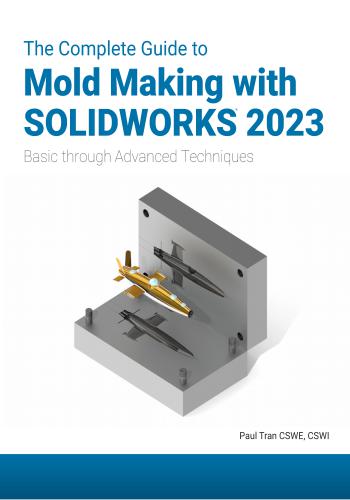
The Complete Guide to Mold Making with SOLIDWORKS 2023 - Basic through Advanced Techniques
Paul Tran
CSWE, CSWI
Sr. Certified SOLIDWORKS Instructor
و المحتوى كما يلي :
TABLE OF CONTENTS
Chapter 1: Plastic Part Design 1-1
Remote Control 1-1
Starting a new part document 1-1
Creating the parent sketch 1-1
Extruding the main body 1-2
Making the upper curved cut 1-2
Adding the fillets 1-3
Shelling the part 1-4
Making the recess sketch 1-5
Making the recess cut 1-6
Copying a sketch 1-7
Creating the mounting bosses 1-8
Adding the support ribs 1-9
Adding the mounting holes 1-10
Adding the rib fillets 1-11
Assigning material 1-12
Changing the part color 1-13
Calculating the mass 1-14
Creating the core and cavity molds 1-15
Applying the scale factor 1-15
Creating the parting lines 1-15
Creating the shut-off surfaces 1-16
Creating the parting surfaces 1-17
Adding a reference plane 1-18
Inserting a tooling split 1-19
Separating the mold blocks 1-20
Hiding the references 1-21
Assigning material to the mold blocks 1-22
Exercise - Plastic part design 2 1-23The Complete Guide to Mold Making with SOLIDWORKS 2023 l Table of Contents
XI
Chapter 2: Surface Repair 2-1
Surface Repair – Mouse 2-1
Opening a parasolid document 2-1
Running Import Diagnostics 2-1
Examining the small surfaces 2-2
Deleting surfaces 2-3
Deleting holes 2-3
Patching the openings 2-4
Adding draft 2-5
Creating a split line feature 2-6
Creating a face fillet 2-7
Adding thickness 2-8
Creating a recess cut 2-9
Saving your work 2-10
Exercise: Repair surfaces 2-11
Chapter 3: Core and Cavity Creation 3-1
Core and Cavity – Plastic Tray 3-1
Opening a part document 3-1
Applying the scale factor 3-1
Creating the parting lines 3-2
Creating a parting surface 3-3
Making the mold block sketch 3-4
Creating a tooling split feature 3-5
Hiding the references 3-6
Assigning materials 3-7
Changing the transparency 3-7
Separating the mold blocks 3-8
Exercise – Creating a Core and Cavity 3-11
Plastic Knob
Opening a part document 3-11
Applying the scale 3-11
Creating the parting lines 3-12
Creating the shut-off surfaces 3-13
Creating the parting surfaces 3-14
Adding a new plane 3-15
Making the sketch of the mold block 3-15
Inserting a tooling split feature 3-16
Separating the mold blocks 3-17The Complete Guide to Mold Making with SOLIDWORKS 2023 l Table of Contents
XII
Chapter 4: Planar Parting Lines 4-1
Planar Parting Lines – Drone’s Canopy 4-1
Opening a part document 4-1
Scaling the part 4-1
Creating the parting lines 4-2
Creating the parting surfaces 4-3
Making the mold block sketch 4-4
Adding the move/copy command 4-5
Separating the mold blocks 4-6
Hiding the references 4-7
Renaming the mold blocks 4-8
Assigning the materials 4-8
Switching to transparency 4-9
Saving your work 4-9
Exercise – Planar Parting Lines 4-11
Drone Cover Housing
Opening a part document 4-11
Scaling the part 4-11
Creating the parting lines 4-12
Creating the parting surfaces 4-13
Adding a new plane 4-14
Making the mold block sketch 4-15
Inserting a tooling split 4-15
Changing materials 4-16
Saving your work 4-16
Chapter 5: Interlock Surface 5-1
Interlock Surface 1 – Stabilizer 5-1
Opening a part document 5-1
Applying the scale factor 5-1
Creating the parting lines 5-2
Creating the parting surfaces 5-3
Making the mold block sketch 5-4
Hiding the references 5-5
Separating the mold blocks 5-6
Changing the transparency 5-7
Interlock Surface 2 – Plastic Cap 5-9
Opening a part document 5-9The Complete Guide to Mold Making with SOLIDWORKS 2023 l Table of Contents
XIII
Applying the scale factor 5-9
Creating the parting lines 5-10
Adding the shut-off surfaces 5-11
Creating the parting surface 5-12
Adding a new plane 5-13
Making the mold block sketch 5-13
Creating a tooling split feature 5-14
Separating the mold blocks 5-15
Hiding the references 5-16
Renaming the solid bodies 5-17
Assigning materials 5-17
Changing the transparency 5-18
Exercise Interlock Surface 3 – Round Knob 5-19
Opening a part document 5-19
Applying the scale factor 5-19
Creating the parting lines 5-20
Creating the parting surfaces 5-21
Adding a new plane 5-22
Making the sketch of the mold block 5-22
Inserting a tooling split feature 5-23
Assigning materials 5-24
Chapter 6: Non-Planar Parting Lines 6-1
Non-Planar parting Lines – Fan Cover 6-1
Opening a part document 6-1
Applying the scale factor 6-1
Creating the parting lines 6-2
Creating the shut-off surfaces 6-3
Creating the parting surfaces 6-4
Adding a new plane 6-4
Sketching the mold block profile 6-5
Splitting the mold blocks 6-5
Hiding the references 6-6
Separating the mold blocks 6-7
Changing the transparency 6-8
Changing the materials 6-9The Complete Guide to Mold Making with SOLIDWORKS 2023 l Table of Contents
XIV
Exercise – Non-Planar Parting Lines 6-11
Meter Reader Upper Housing
Opening a part document 6-11
Applying scale 6-11
Creating the parting lines 6-12
Creating the parting surfaces 6-13
Adding the ruled surfaces 6-14
Closing off the left end 6-15
Extending the lofted surface 6-15
Trimming the left end 6-16
Closing off the right end 6-17
Extending the lofted and ruled surfaces 6-18
Trimming the right end 6-19
Knitting all surfaces 6-20
Creating the shut off surfaces 6-21
Adding a new plane 6-21
Inserting a tooling split feature 6-22
Adjusting the block thickness 6-22
Adding an interlock surface 6-22
Separating the mold blocks 6-23
Changing materials 6-24
Chapter 7: Manual Parting Lines 7-1
Manual Parting Lines - Heat Shield 7-1
Opening a part document 7-1
Applying the scale factor 7-1
Creating the parting lines 7-2
Creating the shut-off surfaces 7-3
Creating the parting surfaces 7-4
Deleting the surfaces 7-5
Creating the ruled surfaces 7-6
Trimming with a sketch 7-7
Making a 3D sketch 7-8
Creating the 1st corner patch 7-9
Patching over corners 7-10
Knitting the surfaces 7-11
Creating a reference plane 7-12
Creating a tooling split 7-13
Separating the mold blocks 7-14
Hiding the references 7-15
Changing the transparency 7-16The Complete Guide to Mold Making with SOLIDWORKS 2023 l Table of Contents
XV
Chapter 8: Undercuts and Slide Cores 8-1
Stress Gauge Upper Housing 8-1
Opening a part document 8-1
Applying the scale factor 8-1
Creating the parting lines 8-2
Creating the shut-off surfaces 8-3
Creating the parting surfaces 8-4
Making the mold block sketch 8-5
Analyzing the undercuts 8-6
Sketching the slide core profile 8-7
Extruding the slide core block 8-8
Separating the mold blocks 8-9
Moving the slide core block 8-10
Hiding the references 8-11
Changing the transparency 8-12
Exercise: Multi-Cavity molds 8-13
Chapter 9: Alternative Methods 9-1
Using Combine Subtract – Rocker Arm 9-1
Opening a part document 9-1
Applying the scale factor 9-1
Making the mold block sketch 9-2
Extruding the mold block 9-2
Creating a combine subtract feature 9-3
Splitting a solid body 9-4
Rotating a solid body 9-5
Using Cut with Surface – Rocker Arm 9-6
Opening a part document
Isolating the surface body 9-6
Making the mold block sketch 9-7
Converting to planar surface 9-8
Trimming the surfaces 9-9
Knitting the surfaces 9-10
Sketching the profile of the mold block 9-11
Cutting with a surface 9-12
Moving a solid body 9-13
Using the Cavity Feature in Assembly 9-14
Opening an assembly document 9-14The Complete Guide to Mold Making with SOLIDWORKS 2023 l Table of Contents
XVI
Inserting the engineered part 9-14
Editing a component 9-15
Inserting a cavity feature 9-15
Creating an exploded view 9-16
Chapter 10: Thickness Analysis 10-1
Thickness Analysis – Medication Upper Case 10-1
Opening a part document 10-1
Setting the parameters 10-1
Analyzing the thickness 10-2
Creating a section view 10-3
Re-arranging the shell feature 10-4
Scaling the part 10-5
Creating the parting lines 10-5
Creating a parting surface 10-6
Adding a new plane 10-7
Making the mold block sketch 10-7
Extruding the mold blocks 10-8
Hiding the references 10-9
Separating the mold blocks 10-10
Changing the transparency 10-11
Chapter 11: Using SOLIDWORKS Plastics 11-1
Plastics Analysis– Basin 11-1
Opening a part document 11-1
Enabling SOLIDWORKS Plastics 11-1
Creating a new study 11-2
Specifying the injection location 11-3
Creating a shell mesh 11-4
Assigning material 11-5
Running the flow analysis 11-6
Viewing the results 11-7
Viewing the report text file 11-9
Chapter 12: SOLIDWORKS Plastics Flow Analysis 12-1
Plastics – Flow Simulation Analysis 12-1
Opening a part document 12-1
Enabling Plastics 12-1The Complete Guide to Mold Making with SOLIDWORKS 2023 l Table of Contents
XVII
Setting up the mesh 12-2
Viewing the PlasticsManager tree 12-2
Adding an injection location 12-3
Creating a mesh 12-4
Selecting a polymer 12-5
Running the flow analysis 12-6
Viewing the fill-time slot 12-7
Animating the results 12-8
Displaying the weld lines 12-9
Viewing the results 12-10
Glossary
Index
Index
3
3-Point-Arc, 1-1, 1-2, 2-6
A
ABS, 1-12, 1-13, 1-22, 2-10, 3-11, 4-1,
4-8, 4-11, 5-1, 5-9, 5-17, 5-19, 6-1, 6-9,
6-11, 6-24, 7-1, 8-1, 10-1
ACIS, 2-1
All contact, 3-13, 8-3
Alternate face, 7-6
Appearance, 1-13
Appearances, 2-9
Assembly cavity, 9-1
B
Blind, 2-9
Block size, 3-5, 3-16, 4-4, 4-15, 5-4, 5-
14, 5-23
Boundary condition, 11-3, 12-2, 12-3
Boundary, 2-7
C
CAD, 2-1
Calculate, 10-1, 10-2
Cap ends, 8-8
Cast alloy steel, 5-5
Cavity block, 3-6, 3-7, 3-9, 3-17, 4-8, 5-
5, 5-6, 5-7, 5-16, 5-17, 5-18, 5-24, 6-8,
6-9, 6-24, 7-14, 7-15, 8-11, 8-12, 10-9,
10-11
Cavity, 3-1, 3-2, 3-3, 3-4, 3-5, 3-8, 9-14,
9-15
Centerlines, 1-9, 10-7
Centroid, 3-1, 3-11, 4-1, 4-11, 5-1, 5-9,
5-19, 6-1, 6-11, 7-1, 8-1, 9-1, 10-5
Chamfer, 9-3
Change transparency, 4-9, 4-16
Change Transparent, 5-18, 7-16
Circle, 5-13, 5-22, 5-23
Circles, 1-8
Color, 1-13, 1-16, 2-10
Combine subtract, 9-1
Combine, 9-1, 9-3
Constant size radius, 1-3, 1-4, 1-11
Constant wall, 10-4
Contact, 5-11, 6-3, 7-3
Convert entities, 9-11
Copy, 1-20
Core block, 3-6, 3-7, 3-17, 4-8, 4-16, 5-
5, 5-6, 5-16, 5-17, 5-24, 6-8, 6-9, 6-24,
7-14, 8-11, 10-9, 10-11
Core, 3-1, 3-2, 3-3, 3-4, 3-5
Core/cavity split, 4-2
Corner rectangle, 1-18, 3-4, 4-4, 4-15, 5-
4, 6-5, 6-22, 8-5, 9-2, 9-7, 10-7
Customize, 4-5
Cut with surface, 9-1, 9-12
Cutting plane, 10-3
D
Delete face, 2-3
Delete hole, 2-3, 2-4
Delta Y, 3-17, 4-6, 5-6, 5-15, 5-23, 6-7,
6-23, 7-14, 8-9, 10-10
Delta Z, 8-10
Dimension, 5-13, 5-22
Dimensions, 1-1, 1-2, 1-8, 1-9, 1-18, 2-9,
3-1, 3-4, 3-8, 3-15, 4-1, 4-4, 4-15, 8-5, 8-
7, 9-1, 9-2, 9-7, 10-7
Direction of pull, 3-2, 3-12, 4-2, 4-12, 5-
2, 5-10, 5-20, 6-2, 6-12, 6-14, 7-2, 8-2,
8-6
Draft analysis, 3-2, 3-12, 4-2, 4-11, 4-12,
5-2, 5-10, 5-20, 6-2, 6-12, 7-2, 8-2, 10-5
Draft angle, 3-2, 3-16, 4-2, 4-12The Complete Guide to Mold Making with SOLIDWORKS 2023 l Index
Index-2
Draft, 1-2, 1-6, 1-7, 1-8, 1-9, 1-10, 1-15,
1-19, 1-23
Drafts, 2-5
E
Edit component, 9-15, 9-16
Ejected, 8-1, 8-6, 8-7
End condition, 8-8
Engineered part, 9-3, 9-5, 9-13, 9-14, 9-
16, 9-17
Equal relation, 1-8, 1-10
Evaluate, 1-14, 8-6, 10-1
Exploded view, 3-8, 3-9, 7-14, 9-16
Extend surface, 6-15, 6-18
Extrude from, 1-7
Extruded boss-base, 1-2, 1-8, 1-9, 9-2, 9-
11
Extruded cut, 1-3, 1-6, 1-7, 1-10, 2-9
F
Face fillet, 2-7
Feature scope, 9-12
FeatureManager, 3-2, 3-12, 5-2, 5-10, 5-
20, 5-22
Features, 1-2, 1-3, 1-4, 1-6, 1-7, 1-8, 1-9,
1-10, 1-11, 1-20
Fill simulation, 11-6
Fill time, 11-6, 11-7, 12-7, 12-10
Fillet, 1-3, 1-4, 1-11, 1-24, 2-7
Flip offset, 1-18, 4-14, 5-13, 5-22, 6-4,
6-21, 10-7
Flow analysis, 11-6, 12-6
Flow Simulation, 12-2, 12-6, 12-10
G
Gap control, 6-20, 7-11
Gaps, 2-1, 2-4
H
Heal all, 2-1
Hide, 1-21, 5-5, 5-16, 6-6, 6-23, 7-15, 8-
11, 10-9
Hide/show, 1-21, 3-6, 6-6, 10-9
Highlight occluded regions, 8-6
Hold line, 2-7
I
IGES, 2-1
Illumination, 4-9
Import diagnostics, 2-1
Injection location, 11-3, 12-3
Injection molding, 10-1
Insert component, 9-14
Interlock surface, 1-19, 3-16, 4-9, 4-14,
5-1, 5-2, 5-7, 5-9, 5-13, 5-14, 5-16, 5-18,
5-19, 5-23, 5-24, 6-2, 6-5, 6-20, 6-22, 7-
13
Isolate, 9-6, 9-11
Isometric view, 7-10, 9-8
K
Knit surface, 6-20, 7-11, 7-12, 9-10, 9-12
Knit, 4-13, 5-11, 5-21
L
Liquid plastics, 5-14
Loft profiles, 6-15, 6-17
Lofted surface, 6-15, 6-17, 7-9
M
Manual mode, 4-3, 4-13, 5-12
Mass properties, 1-14, 10-1
Material, 1-12, 1-22, 2-10, 4-8, 4-16, 6-
9, 6-24, 8-11, 10-1, 10-9, 11-1, 11-3, 11-
5, 12-1, 12-4, 12-5
Materials, 3-7, 4-8, 4-16, 5-17
Melt temperature, 11-3
Merge entities, 6-20, 9-10
Merge result, 1-8, 9-2
Mesh, 11-2, 11-4, 12-2, 12-4, 12-7
Mid-point, 2-6, 10-7The Complete Guide to Mold Making with SOLIDWORKS 2023 l Index
Index-3
Mold block sketch, 5-4, 5-13
Mold blocks, 1-20, 1-22, 4-1, 4-4, 4-6, 4-
7, 4-8, 4-9, 4-14
Mold parameters, 3-2, 3-14, 4-3, 5-3, 5-
10, 5-12, 5-21, 8-4, 10-6
Mold process, 5-13
Mold temperature, 11-3
Mold Tools, 1-15, 1-16, 2-5, 3-1, 3-2, 3-
11, 3-14, 3-16, 4-1, 4-2, 4-4, 4-11, 4-15,
5-1, 5-3, 5-4, 5-9, 5-10, 5-11, 5-19, 5-23,
6-1, 6-2, 6-5, 6-11, 6-21, 7-1, 7-2, 7-6, 7-
13, 8-1, 8-2, 8-8, 9-1, 10-5, 10-8
Mold, 3-1, 3-3, 3-4, 3-5, 3-6, 3-8, 3-15,
3-17
Mounting boss, 1-9, 1-10
Move/copy bodies, 6-7, 6-23, 7-14, 8-9,
8-10, 9-5, 9-13
Move/copy, 3-8, 3-17, 4-5, 4-6, 4-16, 5-
6, 5-14, 5-15, 5-23, 10-10
Mutual, 6-16, 6-19
N
Neutral plane, 2-5
No fill, 5-11, 6-3
Non-planar, 6-1, 6-2, 6-9, 6-11, 7-1, 7-2
O
Offset distance, 10-7
Offset entities, 1-5, 2-9
Offset surface, 9-6
Options, 12-1, 12-7
P
Parasolid, 2-1
Parting lines, 1-1, 1-15, 1-17, 1-21, 1-25,
3-2, 3-12, 4-1, 4-2, 4-7, 4-9, 4-10, 4-11,
4-12, 4-16, 5-1, 5-2, 5-3, 5-5, 5-10, 5-12,
5-13, 5-16, 5-20, 6-1, 6-2, 6-4, 6-6, 6-8,
6-9, 6-11, 6-12, 6-24, 7-1, 7-2, 7-4, 7-15,
8-2, 10-5, 10-9
Parting surface, 3-1, 3-3, 3-4
Parting surfaces, 1-17, 4-3, 4-13, 5-2, 5-
3, 5-10, 5-12, 5-19, 5-21, 6-4, 6-13, 7-4,
7-13, 8-4, 10-6
Patch type, 3-13, 5-11
Perpendicular to pull, 1-17, 3-3, 3-14, 4-
3, 4-13, 5-3, 5-12, 5-21, 6-4, 6-13, 8-4,
10-6
Plain carbon steel, 3-7, 3-17, 4-8, 4-16,
6-9, 6-24, 7-15, 10-9
Planar surface, 9-8, 9-9
Plane, 3-2, 3-12, 3-15, 3-16, 4-14, 5-2, 5-
4, 5-10, 5-13, 5-20, 5-22, 6-4, 6-21, 7-12,
10-7
Plastic injection, 2-5
Plastic part, 1-1, 1-15, 3-6, 4-1, 4-8, 4-9,
4-11, 4-16, 5-5, 5-17, 5-24, 6-8, 6-24, 7-
15, 8-1, 8-11, 9-1, 10-9
Pointer diameter, 12-3
Pressure limit, 11-8, 12-7
Projection, 2-6
R
RealView graphics, 8-11
Recess, 1-5, 1-6, 2-9, 2-10
Reference geometry, 3-15, 4-14, 6-4, 6-
21, 7-12, 10-7
References, 1-21
Ribs, 1-1, 1-9, 1-11
Ruled surfaces, 6-14, 6-15, 6-18, 7-6, 7-
7, 7-8, 7-10
Run simulation, 11-6, 12-2, 12-4
S
Scale factor, 1-15, 6-1, 6-11
Scale, 3-1, 3-11, 4-1, 4-9, 4-11, 5-1, 5-9,
5-19, 6-1, 6-11, 7-1, 8-1, 9-1, 9-15
Section view, 10-3, 10-4
Select tangency, 1-5
Sharp, 3-14, 4-3, 4-13, 5-12, 5-21, 7-4,
8-4, 10-6
Shell mesh, 11-2, 11-4, 12-2, 12-4
Shell, 1-4, 10-4The Complete Guide to Mold Making with SOLIDWORKS 2023 l Index
Index-4
Shrink rate, 5-9, 5-17
Shrinkage, 8-1
Shut-off surface, 3-3, 3-13, 5-11, 8-3
Shut-off surfaces, 1-16, 6-3, 6-11, 6-21,
7-3, 10-6
Side core, 8-1, 8-10
Simulate, 11-1, 12-2, 12-4
Single cavity, 11-1, 12-3
Sketch, 8-5, 8-7, 8-8
Slide core, 8-1, 8-6, 8-7, 8-8, 8-9, 8-10,
8-11, 8-12
Slivers, 2-2
Smoothing, 3-14, 4-3, 4-13, 5-12, 5-21,
8-4, 10-6
Solid bodies folder, 3-6, 3-9, 5-7, 5-24,
8-11, 10-9, 10-11
Solid bodies, 1-21
SOLIDWORKS Plastics, 11-1, 11-2, 12-
1S
plit line, 2-6, 2-7
Split, 9-4
STEP, 2-1
Straddle faces, 8-6
Subtract, 9-1, 9-3, 9-5
Surface bodies folder, 1-21, 3-4, 3-6, 3-
13, 4-7, 4-16, 6-3, 6-6, 6-20, 7-3, 7-11,
7-15, 8-3, 8-11, 9-6, 9-10, 10-9
Surface bodies, 5-5, 5-11, 5-14, 5-16, 5-
23
Surface model, 2-2, 2-3, 2-4, 2-5, 2-8
Surface patch, 7-3
Surfaces, 3-2, 3-3, 3-13, 3-14, 3-17, 4-9,
4-14
Symmetric, 1-9
T
Tangent propagation, 1-4
Tangent, 2-11, 5-11
Taper to vector, 6-14
Target thickness, 10-1
Thick regions, 10-1, 10-2, 10-3
Thicken, 2-8
Thickness analysis, 10-1, 10-2, 10-11
Thickness, 2-8
Thin regions, 10-1, 10-3
Thin walled, 10-1
Through all both, 1-3
Tooling split, 1-18, 1-19, 3-1, 3-4, 3-5,
4-4, 4-9, 4-15, 5-4, 5-14, 5-23, 6-5, 6-22,
7-13, 8-5, 10-8
Translate, 5-15
Transparency, 3-7, 5-7, 5-18, 6-8, 6-24,
8-12, 10-1, 10-11
Transparent, 7-13, 7-15, 7-16
Trapped areas, 8-1, 8-6
Trim surface, 6-16, 6-19, 7-7, 9-9
U
Undercut analysis, 8-1, 8-6
Undercut Faces, 8-6
Undercuts, 8-6
Uniform scaling, 3-11, 4-1, 4-11, 5-1, 5-
19, 6-1, 6-11, 7-1, 8-1, 10-5
Up-to-next, 1-8, 1-9
V
Visibility, 5-18
W
Wall thickness, 1-1STANDARD Toolbar
Creates a new document.
Opens an existing document.
Make Drawing from Part/Assembly.
Make Assembly from Part/Assembly.
Prints the active document.
Print preview.
Cuts the selection & puts it on the clipboard.
Copies the selection & puts it on the clipboard.
Inserts the clipboard contents.
Deletes the selection.
Rebuilds the part / assembly / drawing.
Edits material.
Closes an existing document.
Shows or hides the Selection Filter toolbar.
Shows or hides the Web toolbar.
Properties.
File properties.
Loads or unloads the 3D instant website add-in.
SKETCH TOOLS Toolbar
Sketches a rectangle from the center.
Sketches a centerpoint arc slot.
Sketches a 3-point arc slot.
Sketches a straight slot.
Sketches a centerpoint straight slot.
Sketches a 3-point arc.
Saves an active document.
Reverses the last action.
Redo the last action that was undone.
Saves all documents.
Creates sketched ellipses.
Select tool.
Select the entire document.
Checks read-only files.
Options.
Help.
Full screen view.
OK.
Cancel.
Magnified selection.
Select.
Sketch.
3D Sketch.
SOLIDWORKS Quick GuideSKETCH TOOLS Toolbar
Sets up Grid parameters.
Equation driven curve.
Scales sketch entities.
3D sketch on plane.
Creates a sketch on a selected plane or face.
Sketches a line.
Creates a center point arc: center, start, end.
Creates an arc tangent to a line.
Copies sketch entities.
Sketches 3 point rectangle from the center.
Sketches 3 point corner rectangle.
Sketches a circle.
Sketches a circle by its perimeter.
Makes a path of sketch entities.
Mirrors entities dynamically about a centerline.
Insert a plane into the 3D sketch.
Instant 2D.
Sketch numeric input.
Detaches segment on drag.
Sketch picture.
Partial ellipses.
Sketches a polygon.
Splits a sketch segment.
Converts face curves on the selected face
into 3D sketch entities.
Creates a chamfer between two sketch entities.
Adds a parabola.
Creates a sketch along the intersection of
multiple bodies.
Fillets the corner of two lines.
Creates sketched centerlines.
Adds text to sketch.
Converts selected model edges or sketch
entities to sketch segments.
Extends a sketch segment.
Adds a spline.
Sketches splines on a surface or face.
Sketches a corner rectangle.
Sketches a parallelogram.
Modifies a sketch.
Creates points.
Mirrors selected segments about a centerline.
Creates a sketch curve by offsetting model
edges or sketch entities at a specified distance.
Rotates sketch entities.
Trims a sketch segment.
Construction Geometry.
Creates linear steps and repeat of sketch entities.
Creates circular steps and repeat of sketch entities.
Quick Reference Guide to SOLIDWORKS Command Icons & ToolbarsQuick Reference Guide to SOLIDWORKS Command Icons & Toolbars
Trims or extends structure members.
Adds a fillet weld bead feature.
Creates an end cap feature.
Adds a gusset feature between 2 planar
adjoining faces.
Creates a structure member feature.
WELDMENTS Toolbar
Creates a weldment feature.
Patches surface holes and external edges.
Creates mid surfaces between offset face pairs.
SHEET METAL Toolbar
Shows flat pattern for this sheet metal part.
Shows part without inserting any bends.
Inserts a rip feature to a sheet metal part.
Create a Sheet Metal part or add material to
existing Sheet Metal part.
Inserts a Sheet Metal Miter Flange feature.
Folds selected bends.
Unfolds selected bends.
Inserts bends using a sketch line.
Inserts a flange by pulling an edge.
Inserts a sheet metal corner feature.
Inserts a Hem feature by selecting edges.
Breaks a corner by filleting/chamfering it.
Inserts a Jog feature using a sketch line.
Inserts a lofted bend feature using 2 sketches.
Creates inverse dent on a sheet metal part.
Trims out material from a corner, in a sheet metal
part.
Inserts a fillet weld bead.
Converts a solid/surface into a sheet metal part.
Adds a Cross Break feature into a selected face.
Add a bend from a selected sketch in a Sheet
Metal part.
Sweeps an open profile along an open/closed
path.
Adds a gusset/rib across a bend.
Corner relief.
Welds the selected corner.
Weld bead.
Creates a swept surface.
SURFACES Toolbar
Creates a surface by importing data
from a file.
Creates a lofted surface.
Trims a surface.
Creates a planar surface from a sketch or
a set of edges.
Knits surfaces together.
Creates an extruded surface.
Creates a revolved surface.
Creates an offset surface.
Radiates a surface originating from a
curve, parallel to a plane.
Extends a surface.
Deletes Face(s).
Replaces Face with Surface.
Surface flatten.
Patches surface holes and external edges by
extending the surfaces.
Creates parting surfaces between core &
cavity surfaces.
Inserts ruled surfaces from edges.Quick Reference Guide to SOLIDWORKS Command Icons & Toolbars
Makes a new block.
Edits the selected block.
Inserts a new block to a sketch or drawing.
Adds/Removes sketch entities to/from blocks.
Updates parent sketches affected by this block.
Saves the block to a file.
Explodes the selected block.
Inserts a belt.
BLOCK Toolbar
DIMENSIONS/RELATIONS Toolbar
Creates a horizontal dimension between
selected entities.
Creates a vertical dimension between
selected entities.
Creates a reference dimension between
selected entities.
Adds a geometric relation.
Inserts dimension between two lines.
Creates a set of ordinate dimensions.
Creates a set of Horizontal ordinate
Creates a set of Vertical ordinate dimensions.
Creates a chamfer dimension.
Automatically Adds Dimensions to the current
sketch.
Displays and deletes geometric relations.
Fully defines a sketch.
Scans a sketch for elements of equal length or
radius.
Angular Running dimension.
Display / Delete dimension.
Isolate changed dimension.
Path length dimension.
STANDARD VIEWS Toolbar
Normal to view.
Top view.
Right view.
Bottom view.
Trimetric view.
Dimetric view.
Front view.
Links all views in the viewport together.
Displays viewport with front & right
Displays a 4 view viewport with 1st or
3rd
l f j ti
Displays viewport with front & top.
Displays viewport with a single view.
Isometric view.
Back view.
Left view.
View selector.
New view.Creates a lofted feature between two or
more profiles.
FEATURES Toolbar
Wraps closed sketch contour(s) onto a face.
Adds a deformed surface by push or pull on points.
Creates a filled feature.
Chamfers an edge or a chain of tangent edges.
Inserts a rib feature.
Creates a shell feature.
Applies draft to a selected surface.
Inserts a hole with a pre-defined cross section.
Creates a boss feature by extruding a sketched
profile.
Creates a cut feature by extruding a
sketched profile.
Creates a revolved feature based on profile
and angle parameter.
Creates a cut feature by revolving a
sketched profile.
Thread.
Curve Driven pattern.
Creates a cut by sweeping a closed profile
along an open or closed path.
Creates a cut by thickening one or more
adjacent surfaces.
Creates a solid feature by thickening one or
more adjacent surfaces.
Loft cut.
Applies global deformation to solid or surface
bodies.
Model break view.
Puts a dome surface on a face.
Creates a cylindrical hole.
Combine.
Suppresses the selected feature or component.
Un-suppresses the selected feature or component.
Variable Patterns.
Live Section Plane.
Mirrors.
Instant 3D.
Deletes a solid or a surface.
Joins bodies from one or more parts into a
single part in the context of an assembly.
Hole series.
Inserts a split Feature.
Creates a Sketch Driven pattern.
Creates a Table Driven Pattern.
Moves/Copies solid and surface bodies or
moves graphics bodies.
Scale.
Inserts a part from file into the active
part document.
Moves face(s) of a solid.
Pushes solid / surface model by another
solid / surface model.
Merges short edges on faces.
Flexes solid and surface bodies.
FeatureWorks Options.
Linear Pattern.
Fill Pattern.
Cuts a solid model with a
Boundary Boss/Base.
Boundary Cut.
Circular Pattern.
Recognize Features.
Intersect.
Grid System.MOLD TOOLS Toolbar
Constructs a surface patch.
Applies draft to a selected surface.
Inserts cavity into a base part.
Scales a model by a specified factor.
Inserts a split line feature.
Creates parting lines to separate core & cavity
surfaces.
Creates a planar surface from a sketch or a set of
edges.
Knits surfaces together.
Inserts ruled surfaces from edges.
Inserts a tooling split feature.
Moves face(s) of a solid.
Creates offset surfaces.
Creates parting surfaces between core & cavity
surfaces.
Creates parting surfaces between the core & cavity.
Inserts surface body folders for mold operation.
Creates multiple bodies from a single body.
Extracts core(s) from existing tooling split.
Finds & creates mold shut-off surfaces.
SELECTION FILTERS Toolbar
Turns selection filters on and off.
Adds filter for Sketch Points.
Allows selection for sketch only.
Adds filter for Center Marks.
Adds filter for Centerline.
Adds filter for Solid Bodies.
Adds filter for Notes / Balloons.
Clears all filters.
Inverts current selection.
Selects all filters.
Adds filter for Planes.
Adds filter for Axes.
Adds filter for Surface Bodies.
Allows selection of faces only.
Adds filter for Geometric Tolerances.
Adds filter for Dimensions and Hole Callouts.
Adds filter for Midpoints.
Allows selection filter for vertices only.
Adds filter for blocks.
Adds filter for Cosmetic Threads.
Adds filter for Weld Symbols.
Adds filter for Surface Finish Symbols.
Adds filter for Datum Targets.
Allows selection of edges only.
Adds filter for Sketch Segments.
Adds filter for Datum feature only.
Adds filter for Weld beads.Adds filter for Dowel pin symbols.
Adds filter for connection points.
Adds filter for routing points.
SOLIDWORKS Add-Ins Toolbar
Loads/unloads the Scan-to-3D add-in.
Loads/unloads the SOLIDWORKS Toolbox add-in.
Loads/unloads the Design Checker add-in.
Loads/unloads the PhotoView 360 add-in.
Loads/unloads CircuitWorks add-in.
Loads/unloads the SOLIDWORKS Simulation add-in.
Loads/unloads the SOLIDWORKS Routing add-in.
Loads/unloads the SOLIDWORKS Motions add-in.
Loads/unloads the SOLIDWORKS Plastics add-in.
Loads/unloads the SOLIDWORKS Flow Simulation
add-in.
Loads/unloads the SOLIDWORKS TolAnalysis
add-in.
Creates a lip/groove feature.
Uses sketch elements to create a vent for air flow.
Loads/unloads the SOLIDWORKS MBD SNL
license.
Creates a parameterized snap hook.
Creates a parameterized mounting boss.
Creates a groove to mate with a hook feature.
FASTENING FEATURES Toolbar
EXPLODE LINE SKETCH Toolbar
Adds a route line that connect entities.
Adds a jog to the route lines.
SCREEN CAPTURE Toolbar
Copies the current graphics window to the
clipboard.
Records the current graphics window to an
AVI file.
Stops recording the current graphics window
to an AVI file.
LINE FORMAT Toolbar
Changes line display mode.
Hides / Shows a hidden edge.
Changes the current document layer.
Changes line style.
Changes line thickness.
Changes line color.
Changes layer properties.
2D-To-3D Toolbar
Makes a Front sketch from the selected entities.
Makes a Right sketch from the selected entities.
Makes a Top sketch from the selected entities.
* Ctrl+Q will force a rebuild on
all features of a part.
* Ctrl+B will rebuild the feature
being worked on and its
dependents.Makes a Bottom sketch from the selected entities.
Makes an Auxiliary sketch from the selected entities.
Creates a new sketch from the selected entities.
Repairs the selected sketch.
Aligns a sketch to the selected point.
Creates an extrusion from the selected sketch
segments, starting at the selected sketch point.
Creates a cut from the selected sketch segments,
optionally starting at the selected sketch point.
ALIGN Toolbar
Aligns the bottom side of the selected
annotations with the lowermost annotation.
Aligns the top side of the selected annotations
with the topmost annotation.
Aligns the left side of the selected annotations
with the leftmost annotation.
Makes a Left sketch from the selected entities.
Makes a Back sketch from the selected entities.
Aligns the right side of the selected
annotations with the rightmost annotation.
Creates a group from the selected items.
Evenly spaces the selected annotations vertically.
Centrally aligns the selected annotations vertically.
Centrally aligns the selected annotations horizontally.
Compacts the selected annotations vertically.
Compacts the selected annotations horizontally.
Evenly spaces the selected annotations horizontally.
Deletes the grouping between these items.
Aligns & groups selected dimensions along a
line or an arc.
Aligns & groups dimensions at uniform distances.
SOLIDWORKS MBD Toolbar
MACRO Toolbar
Creates shareable 3D PDF presentations.
Captures 3D view.
Manages 3D PDF templates.
Toggles dynamic annotation views.
Creates a custom macro.
Runs a Macro.
Stops Macro recorder.
Records (or pauses recording of) actions
to create a Macro.
Launches the Macro Editor and begins editing
a new macro.
Opens a Macro file for editing.
Evenly spaces selected dimensions.
Aligns collinear selected dimensions.
Aligns stagger selected dimensions.
SMARTMATES icons
Concentric & Coincident 2 circular edges.
Concentric 2 cylindrical faces.
Coincident 2 linear edges.
Coincident 2 planar faces.
Coincident 2 vertices.
Coincident 2 origins or coordinate systems.ANNOTATIONS Toolbar
Adds a hole table of selected holes from
a specified origin datum.
Adds a Bill of Materials.
Adds a revision table.
Displays a Design table in a drawing.
Adds a weldments cuts list table.
TABLE Toolbar
Adds a Excel based of Bill of Materials
Adds a weldment cut list table.
REFERENCE GEOMETRY Toolbar
Creates a coordinate system.
Creates an axis.
Adds the center of mass.
Specifies entities to use as references
using SmartMates.
Adds a reference plane.
Reduces numbers of points in a selected spline.
Displays curvature combs of selected spline.
Displays minimum radius of selected spline.
Inserts a point to a spline.
Displays all points where the concavity of
selected spline changes.
Adds a curvature control.
Adds a spline based on selected sketch entities
& edges.
Adds a tangency control.
Displays the spline control polygon.
SPLINE TOOLS Toolbar Adds a cosmetic thread to the selected
cylindrical feature.
Inserts a Centerline.
Inserts a hole callout.
Selects and inserts block.
Inserts a datum target symbol and / or
point attached to a selected edge / line.
Inserts a weld symbol on the selected
edge / face / vertex.
Attaches a datum feature symbol to a
selected edge / detail.
Inserts a stacked balloon.
Adds balloons for all components in
selected view.
Attaches a balloon to the selected edge
or face.
Inserts a new geometric tolerancing
symbol.
Inserts a surface finish symbol.
Inserts a note.
Adds center marks to circles on model.
Inserts annotations & reference geometry
from the part / assembly into the selected.
Selects a circular edge or an arc
for Dowel pin symbol insertion.
Inserts a Multi-Jog leader.
Adds a view location symbol.
Inserts latest version symbol.
Adds a cross hatch patterns or solid fill.
Adds a weld symbol on a selected entity.
Adds a weld bead caterpillar on an edge.
Inserts a revision cloud.
Inserts a magnetic line.
Hides/shows annotation.LAYOUT Toolbar
Positions 2 components relative to one another.
Creates a new part from a layout sketch block.
Explodes the selected block.
Saves the block to a file.
Adds / Removes sketch entities to / from a block.
Inserts a new block to the sketch or drawing.
Edits the selected block.
Makes a new block.
Displays / Deletes geometric relations.
Creates a dimension.
Adds a relation.
Mirrors selected entities about a centerline.
Adds sketch entities by offsetting faces,
edges curves.
Trims or extends a sketch.
Rounds a corner.
Sketches a 3 point arc.
Sketches a circle.
Sketches a corner rectangle.
Sketches a line.
Creates the assembly layout sketch.
QUICK SNAP Toolbar
Snap to points.
Snap to center points.
Snap to nearest curve.
Snap to midpoints.
Snap to quadrant points.
Snap to intersection of 2 curves.
Snap parallel to line.
Snap perpendicular to curve.
Snap tangent to curve.
DRAWINGS Toolbar
Updates the selected view to the model’s
current stage.
Creates a section view.
Generates a standard 3-view drawing (1st or 3rd
angle).
Unfolds a new view from an existing view.
Creates a detail view.
Inserts an auxiliary view of an inclined surface.
Adds an Orthogonal or Named view based on
an existing part or assembly.
Adds a Relative view by two orthogonal faces
or planes.
Adds a Predefined orthogonal projected or
Named view with a model.
Creates a Broken-out section.
Crops a view.
Inserts an Alternate Position view.
Adds an empty view.
Adds vertical break lines to selected view.
Snap to angle.
Snap horizontally / vertically to points.
Snap to discrete line lengths.
Snap horizontally / vertically.Changes the display state for the current
configuration.
Rolls the model view.
Turns the orientation of the model view.
Dynamically manipulate the model view in 3D
to make selection.
Changes the display style for the active view.
Displays a shade view of the model with its edges.
Displays a shade view of the model.
Toggles between draft quality & high quality HLV.
Cycles through or applies a specific scene.
Views the models through one of the model’s
cameras.
Displays a part or assembly w/different colors
according to the local radius of curvature.
Displays zebra stripes.
Displays a model with hardware accelerated
shades.
Applies a cartoon affect to model edges &
faces.
Views simulations symbols.
Controls the visibility of coordinate systems.
Controls the visibility of reference curves.
Controls the visibility of sketches.
Controls the visibility of 3D sketch planes.
Controls the visibility of 3D sketch.
Controls the visibility of all annotations.
Controls the visibility of reference points.
Controls the visibility of routing points.
Controls the visibility of lights.
Controls the visibility of cameras.
Controls the visibility of sketch relations.
CURVES Toolbar
Controls the visibility of parting lines.
Controls the visibility of temporary axis.
Controls the visibility of origins.
VIEW Toolbar
Controls the visibility of planes.
Controls the visibility of axis.
Zooms out to see entire model.
Reverts to previous view.
Zooms in by dragging a bounding box.
Zooms to fit all selected entities.
Dynamic view rotation.
Scrolls view by dragging.
Displays image in wireframe mode.
Displays hidden edges in gray.
Displays a view in the selected orientation.
Helical curve defined by a base sketch and
shape parameters.
Creates a composite curve from selected
edges, curves and sketches.
Creates a curve through free points.
Inserts a split line feature.
Projects sketch onto selected surface.
Creates a 3D curve through reference points.
Zooms in or out by dragging up or down.
Displays image with hidden lines removed.
Redraws the current window.TOOLS Toolbar
Inserts or edits a Design Table.
Evaluates section properties for faces and
sketches that lie in parallel planes.
Reports Statistics for this Part/Assembly.
Deviation Analysis.
Checks the model for geometry errors.
Runs the SimulationXpress analysis wizard
powered by SOLIDWORKS Simulation.
Checks the spelling.
Import diagnostics.
Runs the DFMXpress analysis wizard.
Runs the SOLIDWORKSFloXpress analysis wizard.
ASSEMBLY Toolbar
Hides / shows model(s) associated with the
selected model(s).
Creates a new assembly & inserts it into the
assembly.
Turns on/off large assembly mode for this document.
Adds an existing part or sub-assembly to the
assembly.
Toggles the transparency of components.
Toggles between editing part and assembly.
Changes the selected components to
suppressed or resolved.
Creates a new part & inserts it into the
assembly.
Inserts a belt.
Adds or edits equation.
Calculates the mass properties of the model.
Calculates the distance between selected
items.
Replaces mate entities of mates of the selected
components on the selected Mates group.
Replaces selected components.
Shows or Hides the Simulation toolbar.
Rotates an un-mated component around its
center point.
Interference detection.
Sketch driven component pattern.
Creates or edits explode line sketch.
Creates a New Exploded view.
To add or remove an icon
to or from the toolbar, first select:
Tools/Customize/Commands
Next, select a Category, click a button to
see its description and then drag/drop the
command icon into any toolbar.
Patterns components in one or two
linear directions.
Patterns components around an axis.
Sets the transparency of the components
other than the one being edited.
Curve driven component pattern.
SmartMates by dragging & dropping components.
Checks assembly hole alignments.
Mirrors subassemblies and parts.
External references will not be created.
Positions two components relative to one
another.
Moves a component.
Smart Fasteners.
Pattern driven component pattern.
Chain driven component pattern.SOLIDWORKS Quick-Guide
STANDARD Keyboard Shortcuts
* Horizontally or Vertically: Arrow keys
* Horizontally or Vertically 90º: Shift + Arrow keys
* Clockwise or Counterclockwise:
Alt + left or right Arrow
* Pan the model:
Ctrl + Arrow keys
* Zoom in:
Z (shift + Z or capital Z)
* Zoom out: z (lower case z)
* Zoom to fit:
F
* Previous view:
Ctrl+Shift+Z
* View Orientation Menu:
Space bar
* Front: _ Ctrl+1
* Back:
Ctrl+2
* Left:
Ctrl+3
* Right: Ctrl+4
* Top: Ctrl+5
* Bottom:
Ctrl+6
* Isometric:
Ctrl+7
* Filter Edges: e
* Filter Vertices: v
* Filter Faces: x
* Toggle Selection filter toolbar: _ F5
* Toggle Selection Filter toolbar (on/off): F6
* New SOLIDWORKS document: F1
* Open Document: _ Ctrl+O
* Open from Web folder: Ctrl+W
* Save: Ctrl+S
* Print: Ctrl+P
* Magnifying Glass Zoom _ g
* Switch between the SOLIDWORKS documents _ Ctrl + Tab
SOLIDWORKS 2023 Quick-Guides:
Quick Reference Guide to SOLIDWORKS 2023 Command Icons and Toolbars
SOLIDWORKS Sample Customized Hot Keys
Function Keys
F1 SW-Help F2 2D
Sketch F3 3D Sketch F4
Modify
F5 Selection Filters F6
Move (2D Sketch) F7 Rotate (2D Sketch) F8
Measure
F9 Extrude F10 Revolve
F11 Sweep F12 Loft
Sketch
C Circle
P Polygon E Ellipse
O Offset Entities Alt + C
Convert Entities M Mirror
Alt + M Dynamic Mirror
Alt + F Sketch Fillet T
Trim
Alt + X Extend
D Smart Dimension Alt + R
Add Relation
Alt + P Plane
Control + F Fully Define Sketch Control + Q
Exit Sketch
#Solidworks,,#Tutorial,,#سولدورك,,#سولدوركس,,#سولدوورك,,#سولدووركس,,#سوليدورك,,#سوليدوركس,
,#سوليدوورك,,#سوليدووركس,#سولد_ورك,#سوليد_وركس,#,#سولد_وركس,#سوليد_ورك,#,#سولد_ورك,
كلمة سر فك الضغط : books-world.net
The Unzip Password : books-world.net
أتمنى أن تستفيدوا من محتوى الموضوع وأن ينال إعجابكم
رابط من موقع عالم الكتب لتنزيل كتاب The Complete Guide to Mold Making with SOLIDWORKS 2023 - Basic through Advanced Techniques
رابط مباشر لتنزيل كتاب The Complete Guide to Mold Making with SOLIDWORKS 2023 - Basic through Advanced Techniques 
|
|


