Admin
مدير المنتدى


عدد المساهمات : 18717
التقييم : 34685
تاريخ التسجيل : 01/07/2009
الدولة : مصر
العمل : مدير منتدى هندسة الإنتاج والتصميم الميكانيكى
 |  موضوع: رسالة ماجستير بعنوان Design, Simulation, and Fabrication of a Lightweight Magneto Rheological Damper الإثنين 30 نوفمبر 2020 - 11:11 موضوع: رسالة ماجستير بعنوان Design, Simulation, and Fabrication of a Lightweight Magneto Rheological Damper الإثنين 30 نوفمبر 2020 - 11:11 | |
| 
أخوانى فى الله
أحضرت لكم
رسالة ماجستير بعنوان
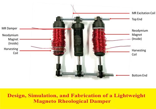
Design, Simulation, and Fabrication of a Lightweight Magneto Rheological Damper
By
Soroush Sefidkar-Dezfouli
B.Sc., Azad University, 2009
Thesis Submitted in Partial Fulfilment of the Requirements for the Degree of Master of Applied Science
In the
School of Mechatronic Systems Engineering Faculty of Applied Sciences
و المحتوى كما يلي :
Table of Contents
Approval ii
Partial Copyright License . iii
Abstract iv
Dedication . v
Acknowledgements vi
Table of Contents vii
List of Tables . x
List of Figures . xi
Chapter 1. Introduction .1
1.1. Mountain bicycle rear suspension system 2
1.1.1. Conventional shocks .3
1.1.2. Semi-active shocks .4
1.2. Research motivation and contributions .5
1.3. Fabrication and assembly of a prototype MR damper Thesis outline 6
Chapter 2. Review of MR Fluid and MR Damper Mechanism .7
2.1. MR Fluid .7
2.1.1. MR Fluid components and composition .8
2.1.2. MR fluid magnetic behaviour .10
Magnetic material 10
Concept of electromagnetism 13
MR Fluid magnetic properties .14
2.1.3. Rheology of MR fluid .15
Basics of rheology .15
Rheological properties of MR fluid 18
MR fluid models 20
Bingham plastic model 21
Herschel-Bulkley plastic model .22
2.1.4. MR Fluid modes and applications .23
Valve mode .23
Shear mode 25
MR Brakes .26
Squeeze mode 27
MR fluid elastomer mount .28
2.2. MR Damper 29
2.2.1. MR damper components and designs .29
Cylinder structures 30
Monotube damper structure 30
Twin tube structure 31
Double-ended structure .32
Valve structure 33
Single coil valves .34
Multi coil valves .36
Perpendicular coil axis valve .36viii
Valve with both annular and radial flow channel .37
Fail-safe MR dampers .38
2.2.2. MR damper modeling 40
Quasi-static models 40
Axisymmetric models 41
Parallel plate model .42
Dynamic models .44
Parametric dynamic model 44
Bingham dynamic model . 45
Bouc-wen and Spencer dynamic models 45
Non-parametric dynamic model 47
2.3. Conclusion .48
Chapter 3. Experimental comparison of MR and conventional dampers 49
3.1. Feasibility Testing .49
3.1.1. Test mechanism 50
3.1.2. Damper selection 52
3.1.3. Test procedure and guidelines 53
General Guidelines for testing all the dampers: .54
Guidelines for testing conventional dampers (D1, D2, and D3): 54
Guidelines for testing the MR damper .54
3.2. Analysis of results 56
3.2.1. Data acquisition and Performance evaluation .57
Effect of input stimuli amplitude on performance .57
Input stimuli frequency effect on performance .58
Rebound circuit and compression circuit effect on performance 59
Effect of the Input current on performance 61
Effect of the parallel coil spring on performance 61
3.2.2. Proof of feasibility 63
3.3. Conclusion .64
Chapter 4. Design, Simulation, and Optimization .65
4.1. Study of two commercial dampers 65
Fox Van R Downhill Shock absorber .65
Lord 8041 MR Damper 69
4.2. Optimal design of an MR damper .73
4.2.1. Material selection 73
4.2.2. Magnetic field analysis of MR damper .76
4.2.3. Finite element simulation 77
Approach and Assumptions 78
Output data .82
4.2.4. Optimization using finite element analysis .82
Optimization objectives .84
Design parameters and constraint selection 87
Genetic algorithm for optimum design .89
Results analysis 90
4.2.5. Coil wire selection .93ix
4.1. Conclusion .97
Chapter 5. Fabrication and testing of a prototype MR damper 98
5.1. Materials, sealing, CAD design, and prototyping 98
5.2. Experimental performance testing 103
5.2.1. Effect of displacement amplitude .103
5.2.2. Effect of displacement frequency 104
5.2.3. Effect of input current 105
5.2.4. Comparison of parallel plate model and experimental data .105
5.2.5. Comparison of Lord MR damper and prototype MR damper .106
5.3. Conclusion .107
Chapter 6. Summary and future works 108
6.1. Research summery 108
6.2. Recommendations for future work 110
References 112
Appendix A. Experimental test results for four tested shocks 119
Appendix B SolidWorks drawings of prototype. 122
Appendix C MRF132DG Datasheet 124x
List of Tables
Table 3.1 All performed tests, over a wide range of input displacement profiles. .55
Table 4.1 Material available for Cylinder body .74
Table 4.2 Commercial MR fluid available. .75
Table 4.3 Design parameters of Lord MR damper .82
Table 4.4 Constants and intermediate variables 88
Table 4.5 Design variables and parameters constraints. .89
Table 4.6 Optimization results for design variables and main properties. 91
Table 4.7 AWG wire properties and calculated performance. 96
Table 5.1 List of components utilized in prototype. 99
Table 5.2 Parameter comparison of Lord MR damper and prototype. .106xi
List of Figures
Figure 2.1 (a) MRF in absence of a magnetic field, (b) MRF particle alignment
under influence of magnetic field 7
Figure 2.2 Powder metallurgy process main stages. .9
Figure 2.3 Typical hysteresis loop for a ferromagnetic material. 11
Figure 2.4 Comparison of soft and hard magnetic material hysteresis curve. 12
Figure 2.5 (a) Solenoid coil wounded around the air (b) Solenoid wounded
around a soft magnetic core .13
Figure 2.6 B-H curve of MRF132DG MR fluid by Lord Corp. .15
Figure 2.7 Shear force applied to a surface[30] .16
Figure 2.8 Rheological behavior of various viscous materials 17
Figure 2.9 MRF132DG Lord Corp MR fluid (a) Shear stress Vs Shear rate (b)
Yield stress Vs Magnetic field intensity .19
Figure 2.10 (a) stress-strain of MR fluid (b) Bingham model of MR fluid. .21
Figure 2.11 Herschel-Bulkley model of MR fluid. .22
Figure 2.12 (a) concept of valve mode (b) Bingham velocity profile of MR fluid in
valve mode [19](c) flow through a parallel duct [48] 24
Figure 2.13 (a) concept of direct shear mode [19] (b) Bingham velocity profile of
MR fluid in shear mode [15]. 25
Figure 2.14 Major MR-brake designs: (a) drum (b) inverted drum (c) T-shaped
rotor(d) disk (e) multiple disks. .27
Figure 2.15 Concept of squeeze mode[19] 27
Figure 2.16 (a) Rubber puck shape vibration mount (b) new polyruretane
membrane for vibration mount application[44] 29
Figure 2.17 Mono tube cylinder[8]. 31
Figure 2.18 (a) conceptual structure of twin-tube[51] (b)foot valve sectional view
[8] (c) section view of a twin tube damper[8] .32
Figure 2.19 Double-end MR damper[8]. 33xii
Figure 2.20 (a) Typical control valve of MR damper[48] (b) MR damper with
external stationary coil[17] 35
Figure 2.21 (a) Single coil valve mode MR damper[88] (b) Single coil valve in
shear mode (c) Single coil valve in valve mode 35
Figure 2.22 (a) Multi coil MR damper [42] (b) schematics of double coil MR
damper .36
Figure 2.23 (a) Components of perpendicular coil axis configuration (b) core
structure (c) Magnetic field path in perpendicular coil axis
configuration [52] 37
Figure 2.24 (a) Detailed schematics of valve with both annular and radial flow
channel [59] (b) Flow path and magnetic field of damper [48] .38
Figure 2.25 (a) Implementation of permanent magnets in poles of MR damper
only(b) magnetic core structure with permanent magnet (c) failsafe hybrid damper with permanent magnets inside core and
poles [55]. 39
Figure 2.26 Schematics of a valve mode MR damper piston with geometrical
parameters .44
Figure 2.27 (a) Bingham model (b) Bingham body model (c)Bingham and
Bingham body model Force-velocity curve .46
Figure 2.28 (a) Bouc-wen model for MR damper (b) Spencer model for MR
damper [75] 47
Figure3.1 (a) Hydraulic shaker, (b) Force transducer, (c) Digital controller. .50
Figure 3.2 Fabricated connector to attach dampers to the hydraulic shaker. .51
Figure 3.3 Test mechanism components, while testing MR damper in parallel
with coil spring. 51
Figure 3.4 Tested Shocks: (a) Fox Van R (D1), (b) Fox Van RC (D2), (c) Cane
Creek Double Barrel (D3), (d) Lord Corporation MR damper 53
Figure 3.5 Experimental results (a) the force-displacement curve for a
conventional bicycle damper (b) the force-velocity curve for a
conventional bicycle damper. .57
Figure 3.6 Force vs. Displacement in High Rebound (HR)- Low Compression
(LR) with 2Hz frequency and different amplitudes: (a) D1 (b) D2
(c) D3 (d) MR damper. .58xiii
Figure 3.7 (a) F-V curve of D3 damper for different frequencies at 23mm
amplitude, (b) F-V curve of MR damper for different frequencies at
23mm amplitude .59
Figure 3.8 Comparison of the effect of knob adjustment: (a) F-D of D1 for LR and
HR, (b) F-V of D1 for LR and HR, (c) F-D of D2 for LR and HR, (d)
F-D of D2 for LR and HR, (e) F-D of D3 for LR and HR ,(f) F-D of
D3 for LR and HR .60
Figure 3.9 MR damper characteristics for different input currents (6Hz, 23mm):
(a) F-D curve, (b) F-V curve. 61
Figure 3.10 Results for MR with spring (current: 0.8 A; amplitude: 08 and 13 mm;
frequency: 2 and 4 Hz): (a) F-D characteristic, (b) F-V
characteristic. Comparison of MR characteristic with and without
spring (current: 0.8 A; amplitude: 13 mm; frequency: 4 Hz): (c) F-D
curve, (d) F-V curve. 62
Figure 3.11 Comparison of results for MR and D3 dampers (Without Spring;
amplitude: 13 mm; frequency: 4 Hz): (a) F-D curve, (b) F-V curve 63
Figure 4.1 Detailed dissection of Fox Van R shock absorber .66
Figure 4.2 (a) Rod and rebound adjustment mechanism, (b) cylinder cap and
bottom out bumper, (c) Piston and shim stacks, (d) compression
and rebound valves, (e) cylinder and preload ring, (f) Coupler and
compression adjustment knob, (g) gas chamber cylinder and
pressure valve, (h) Floating piston. 68
Figure 4.3 Detailed dissection of Fox Van R shock absorber .70
Figure 4.4 Spectrometry result for cylinder material (peaks showing Fe, O, C) 71
Figure 4.5 (a) Rod handle with bushing and wires, (b) Piston housing, wear strip,
and guides, (c) Coil, (d) Magnetic pole and hallow core with coil
slot, (e) Rubber diaphragm and cap, (f) MR fluid flow gap filled
with MR. .fluid. .72
Figure 4.6 MR valve magnetic links and magnetic path .77
Figure 4.7 (a) SolidWorks CAD model of the Lord 8041 MR damper, (b) Imported
3D model using LiveLink, (c) 2D model in Comsol. 78
Figure 4.8 MR damper selected design with DVs. .79
Figure 4.9 (a) HB curve of Comsol materials library, (b) MR fluid HB curve from
Comsol obtained from datasheet 80
Figure 4.11 (a) 3D simulation to study x density for Lord MR damper, (b) 2D
simulation of flux density for Lord MR damper 81xiv
Figure 4.10 Customised meshing used for FEA simulation 81
Figure 4.12 Optimization procedure flow chart. .83
Figure 4.13 Optimization design variables and dependent parameters. 87
Figure 4.14 (a) Flux density distribution for initial values, (b) Flux density
distribution for optimized values. 92
Figure 4.15 (a) The maximum damping force in optimization generations, (a)
bottom weight values in different iterations (b) top Volume of MR
used in damper in different generations (b) bottom, dynamic ratio
in generations. .93
Figure 5.1 Detailed SolidWorks CAD design of proposed damper .100
Figure 5.2 Prototype (a) Cylinder and caps (b) Rod-end cylinder cap 100
Figure 5.3 Prototype (a) Gas chamber-end cylinder cap with high pressure valve
(b) Floating piston. .101
Figure 5.4 Prototype (a) wounded coil (b) Assembled piston .102
Figure 5.5 Prototype MR damper (a) Assembled part without cylinder (b)
Assembled MR damper 103
Figure 5.6 Magnetic core and poles design. 103
Figure 5.7 Amplitude change effect for prototype MR damper (a) FD curves (b)
FV curves .104
Figure 5.8 Frequency effect for prototype MR damper (a) FD curves (b) FV
curves. .104
Figure 5.9 Input current effect for prototype MR damper (a) FD curves (b) FV
curves. .105
Figure 5.10 Comparison of max damping force for predicted model and
experimental data (a) low velocity @ 0.018 (m/s) (b) high velocity
@ 0.867 (m/s). .106
Figure 5.11 Comparison of Lord MR damper and prototype (a) FD curve showing
passive force comparison (b) FV curve showing passive force
comparison (c) FD curve showing total force comparison (d) FV
curve showing total force comparison
كلمة سر فك الضغط : books-world.net
The Unzip Password : books-world.net
أتمنى أن تستفيدوا من محتوى الموضوع وأن ينال إعجابكم
رابط من موقع عالم الكتب لتنزيل رسالة ماجستير بعنوان Design, Simulation, and Fabrication of a Lightweight Magneto Rheological Damper
رابط مباشر لتنزيل رسالة ماجستير بعنوان Design, Simulation, and Fabrication of a Lightweight Magneto Rheological Damper 
|
|


