Admin
مدير المنتدى


عدد المساهمات : 18745
التقييم : 34763
تاريخ التسجيل : 01/07/2009
الدولة : مصر
العمل : مدير منتدى هندسة الإنتاج والتصميم الميكانيكى
 |  موضوع: كتاب Introduction to Finite Element Analysis Using SOLIDWORKS Simulation الجمعة 03 يونيو 2022, 1:25 am موضوع: كتاب Introduction to Finite Element Analysis Using SOLIDWORKS Simulation الجمعة 03 يونيو 2022, 1:25 am | |
| 
أخواني في الله
أحضرت لكم كتاب
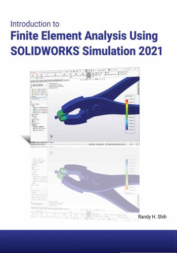
Introduction to Finite Element Analysis Using SOLIDWORKS Simulation 2021
Randy H. Shih
Oregon Institute of Technology
و المحتوى كما يلي :
Table of Contents
Preface
Acknowledgments
Introduction
Introduction
Development of Finite Element Analysis
FEA Modeling Considerations
Types of Finite Elements
Finite Element Analysis Procedure
Matrix Definitions
Getting Started with SOLIDWORKS
Starting SOLIDWORKS
SOLIDWORKS Screen Layout
• Menu Bar Toolbar
• Menu Bar Pull-down Menus
• Heads-up View Toolbar
• Features Toolbar
• Sketch Toolbar
• Feature Manager Design Tree
• Graphics Area
• Reference Triad
• Origin
• Confirmation Comer
• Graphics Cursor or Crosshairs
• Message and Status Bar
Using the SOLIDWORKS Command Manager
Mouse Buttons
[Esc]- Canceling Commands
SOLIDWORKS Help System
Leaving SOLIDWORKS
Create a CAD Files Folder
Intro-2
Intro-2
Intro-3
Intro-4
Intro-6
Intro-6
Intro-9
Intro-9
Intro-12
Intro-12
Intro-13
Intro-13
Intro-13
Intro-13
Intro-14
Intro-15
Intro-15
Intro-15
Intro-15
Intro-15
Intro-15
Intro-16
Intro-17
Intro-17
Intro-18
Intro-18
Intro-19
Chapter 1
The Direct Stiffness Method
Introduction
One-dimensional Truss Element
Example 1.1
Example 1.2
Basic Solid Modeling Using SOLIDWORKS
The Adjuster Design
1-2
1-3
1-5
1-7
1-10
1-10iv Introduction to Finite Element Analysis
Starting SOLIDWORKS
Step 1: Create a Rough Sketch
Graphics Cursors
Geometric Relation Symbols
Step 2: Apply/Modify Relations and Dimensions
Viewing Functions- Zoom and Pan
Delete an Existing Geometry of the Sketch
Modify the Dimensions of the Sketch
Step 3: Complete the Base Solid Feature
Isometric View
Rotation of the 3D Model- Rotate View
Rotation and Panning- Arrow Keys
Dynamic Viewing- Quick Keys
3D Rotation
Viewing Tools- Heads-up View Toolbar
View Orientation
Display Style
Orthographic vs. Perspective
Customize the Heads-up View Toolbar
Step 4-1: Adding an Extruded Boss Feature
Step 4-2: Adding an Extruded Cut Feature
Step 4-3: Adding another Cut Feature
Save the Model
Questions
Exercises
1-10
1-12
1-12
1-14
1-15
1-17
1-18
1-19
1-20
1-21
1-21
1-23
1-24
1-26
1-26
1-27
1-28
1-28
1-28
1-29
1-33
1-35
1-37
1-38
1-39
Chapter 2
Truss Elements in Two-Dimensional Spaces
Introduction
Truss Elements in Two-Dimensional Spaces
Coordinate Transformation
Example 2.1
Solution
Global Stiffness Matrix
Example 2.2
Solution
Questions
Exercises
2-2
2-2
2-5
2-9
2-10
2-10
2-13
2-13
2-19
2-20
Chapter 3
2D Trusses in MS Excel and Truss Solver
Direct Stiffness Matrix Method using Excel
Example 3.1
3-2
3-2Table of Contents v
Establish the Global K Matrix for each Member
Assembly of the Overall Global Stiffness Matrix
Solving the Global Displacements
Calculating Reaction Forces
Determining the Stresses in Elements
The Truss Solver and the Truss View Programs
The Truss View Program
Questions
Exercises
3-3
3-8
3-10
3-16
3-18
3-23
3-30
3-32
3-33
Chapter 4
Truss Elements in SOLIDWORKS Simulation
One-dimensional Line Elements
Starting SOLIDWORKS
Units Setup
Creating the CAD Model- Solid Modeling Approach
A CAD Model is NOT an FEA Model
The SOLIDWORKS Simulation Module
Creating an FEA Model
Assign the Element Material Property
Apply Boundary Conditions - Constraints
Apply External Loads
Create the FEA Mesh and Run the Solver
Viewing the Stress Results
Viewing the Displacement Results
Questions
Exercises
4-2
4-4
4-5
4-6
4-15
4-16
4-17
4-19
4-20
4-23
4-25
4-26
4-28
4-29
4-30
Chapter 5
SOLIDWORKS Simulation Two-Dimensional Truss Analysis
Finite Element Analysis Procedure
Preliminary Analysis
Starting SOLIDWORKS
Units Setup
Creating the CAD Model- Structural Member Approach
Creating Structural Members in SOLIDWORKS
Weldment Profiles
Activate the SOLIDWORKS Simulation Module
Setting Up Truss Elements
Assign the Element Material Property
Applying Boundary Conditions - Constraints
Applying External Loads
Create the FEA Mesh and Run the Solver
5-2
5-3
5-4
5-5
5-6
5-8
5-9
5-12
5-14
5-15
5-16
5-21
5-23vi Introduction to Finite Element Analysis
Viewing the Stress results
Viewing the Internal Loads of All members
Viewing the Reaction Forces at the supports
Questions
Exercises
5-24
5-26
5-27
5-28
5-29
Chapter 6
Three-Dimensional Truss Analysis
Three-Dimensional Coordinate Transformation Matrix
Stiffness Matrix
Degrees of Freedom
Problem Statement
Preliminary Analysis
Start SOLIDWORKS
Units Setup
Create the CAD Model- Structural Member Approach
Create a New Weldment Profile in SOLIDWORKS
Create Structural Members using the New Profile
Editing the Dimensions of the New Profile
Activate the SOLIDWORKS Simulation Module
Setting Up the Truss Elements
Assign the Element Material Property
Applying Boundary Conditions - Constraints
Applying the External Load
Create the FEA Mesh and Run the Solver
Using the Probe Option to View Individual Stress
Viewing the Internal Loads of All Members
Questions
Exercises
6-2
6-3
6-3
6-5
6-5
6-7
6-8
6-9
6-12
6-17
6-19
6-20
6-22
6-23
6-24
6-25
6-27
6-28
6-29
6-30
6-31
Chapter 7
Basic Beam Analysis
Introduction
Modeling Considerations
Problem Statement
Preliminary Analysis
Start SOLIDWORKS
Units Setup
Create the CAD Model- Structural Member Approach
Create a Rectangular Weldment Profile
Create Structural Members Using the New Profile
Adjust the Orientation of the Profile
7-2
7-2
7-3
7-3
7-6
7-7
7-8
7-10
7-14
7-15Table of Contents vii
Add a Datum Point for the Concentrated Load
Activate the SOLIDWORKS Simulation Module
Assign the Element Material Property
Apply Boundary Conditions - Constraints
Apply the Concentrated Point Load
Apply the Distributed Load
Create the FEA Mesh and Run the Solver
What Went Wrong?
Directions 1 and 2 in Shear and Moment Diagrams
Questions
Exercises
7-16
7-18
7-20
7-21
7-24
7-26
7-28
7-29
7-32
7-34
7-35
Chapter 8
Beam Analysis Tools
Introduction
Problem Statement
Preliminary Analysis
Stress Components
Start SOLIDWORKS
Create the CAD Model- Structural Member Approach
Create a Rectangular Weldment Profile
Create Structural Members Using the New Profile
Adjust the Orientation of the Profile
Add a Datum Point for the 1.5m Location
Activate the SOLIDWORKS Simulation Module
Assign the Element Material Property
Apply Boundary Conditions - Constraints
Apply the Distributed Load
Create the FEA Mesh and Run the Solver
Shear and Moment Diagrams
Using the Probe Option to Examine Stress at Pointl
Questions
Exercises
8-2
8-2
8-3
8-4
8-6
8-7
8-9
8-13
8-14
8-15
8-17
8-19
8-20
8-23
8-25
8-26
8-28
8-29
8-30
Chapter 9
Statically Indeterminate Structures
Introduction
Problem Statement
Preliminary Analysis
Start SOLIDWORKS
Create the CAD Model
Create a Circular Weldment Profile
9-2
9-3
9-3
9-6
9-7
9-9viii Introduction to Finite Element Analysis
Create Structural Members using the New Profile
Add a Datum Point for the Concentrated Load
Activate the SOLIDWORKS Simulation Module
Assign the Element Material Property
Apply Boundary Conditions - Constraints
Apply the Concentrated Point Load
Create the FEA Mesh and Run the Solver
Viewing the Internal Loads of All members
Shear and Moment Diagrams
Questions
Exercises
9-13
9-14
9-16
9-18
9-19
9-22
9-24
9-25
9-26
9-28
9-29
Chapter 10
Two-Dimensional Surface Analysis
Introduction
Problem Statement
Preliminary Analysis
• Maximum Normal Stress
• Maximum Displacement
Geometric Considerations of Finite Elements
Start SOLIDWORKS
Create the CAD Model
Activate the SOLIDWORKS Simulation Module
Assign the Element Material Property
Apply Boundary Conditions - Constraints
Apply the External Load
H-Element versus P-Element
Create the first FEA Mesh-Coarse Mesh
Run the Solver
Refinement of the FEA Mesh-Global Element Size 0.10
Refinement of the FEA Mesh-Global Element Size 0.05
Refinement of the FEA Mesh-Global Element Size 0.03
Refinement of the FEA Mesh- Global Element Size 0.02
Comparison of Results
Questions
Exercises
10-2
10-3
10-3
10-3
10-4
10-5
10-6
10-7
10-10
10-13
10-14
10-17
10-18
10-19
10-21
10-23
10-25
10-27
10-28
10-29
10-30
10-31
Chapter 11
Three-Dimensional Solid Elements
Introduction
Problem Statement
Preliminary Analysis
11-2
11-3
11-4Table of Contents ix
Start SOLIDWORKS
Create a CAD Model in SOLIDWORKS
> Define the Sweep Path
> Define the Sweep Section
r* Create the Swept Feature
> Create a Cut Feature
Activate the SOLIDWORKS Simulation Module
Assign the Element Material Property
Apply Boundary Conditions-Constraints
Apply the External Load to the system
Create the first FEA Mesh- Coarse Mesh
Run the Solver
Refinement of the FEA Mesh- Global Element Size 0.10
Refinement of the FEA Mesh- Mesh Control Option
Refinement of the FEA Mesh- Automatic Transition
Comparison of Results
Questions
Exercises
11-7
11-8
11-8
11-10
11-12
11-13
11-15
11-17
11-18
11-19
11-20
11-22
11-24
11-26
11-29
11-31
11-32
11-33
Chapter 12
3D Thin Shell Analysis
Introduction
Problem Statement
Preliminary Analysis
Start SOLIDWORKS
Create a 3D Solid Model in SOLIDWORKS
Activate the SOLIDWORKS Simulation Module
Assign the Element Material Property
Apply Boundary Conditions- Constraints
Apply the Pressure to the System
Create the first FEA Mesh- Coarse Mesh
Run the Solver and View the Results
Refinement of the FEA Mesh- Global Element Size 12.5
Start a New 3D Surface Model
Start a New FEA Study
Completing the Definition of the Surface Model
Assign the Element Material Property
Apply Boundary Conditions- Constraints
Apply the Pressure to the System
Create the first FEA Mesh- Coarse Mesh
Run the Solver and View the Results
Refinement of the FEA Mesh- Global Element Size 10.0
Notes on FEA Linear Static Analyses
Questions
12-2
12-4
12-4
12-6
12-7
12-9
12-11
12-12
12-14
12-15
12-16
12-17
12-18
12-21
12-22
12-23
12-24
12-28
12-29
12-30
12-31
12-32
12-33x Introduction to Finite Element Analysis
Exercises 12-34
Chapter 13
FEA Static Contact Analysis
Introduction
Problem Statement
Parts
(1) Pliers-Jaw
(2) Pin
(3) Fork
Start SOLIDWORKS
Document Properties
Insert the First Component
Insert the Second Component
Assembly Mates
Insert the Third Component
Insert the Upper Jaw Component
Identifying Coincident Surfaces in the Model
Activate the SOLIDWORKS Simulation Module
Assign the Element Material Property
Apply Boundary Conditions- Constraints
Apply the External Load on the Handles
Global Contact Settings
Set up Specific Local Contact Sets
Set up the Contact Set on the PIN part
Set up the Contact Set on the two Plier-Jaw parts
Create the FEA Mesh
Run the Solver and View the Results
Use the Animate Option
Refinement of the FEA Mesh- Apply Mesh Control
Use the Section Clipping Option
Use the Iso Clipping Option
Set up a Contact Pressure Plot
Questions
Exercises
13-2
13-3
13-4
13-4
13-6
13-6
13-8
13-8
13-9
13-10
13-11
13-14
13-16
13-19
13-20
13-22
13-23
13-24
13-25
13-26
13-28
13-30
13-31
13-32
13-34
13-35
13-37
13-38
13-39
13-42
13-43
Chapter 14
Dynamic Modal Analysis
Introduction
Problem Statement
Preliminary Analysis
The Cantilever Beam Modal Analysis Program
14-2
14-3
14-3
14-6Table of Contents xi
Start SOLIDWORKS
Create the CAD Model
Activate the SOLIDWORKS Simulation Module
Assign the Element Material Property
Apply Boundary Conditions- Constraints
Create the first FEA Mesh
Viewing the Results
Refinement of the FEA Mesh- Global Element Size 0.15
Add an Additional Mass to the System
One-Dimensional Beam Frequency Analysis
Conclusions
Questions
Exercises
14-9
14-10
14-12
14-14
14-15
14-16
14-18
14-21
14-23
14-27
14-28
14-29
14-30
Appendix
IndexIntroduction to Finite Element Analysis 1-1
INDEX
A Dimension, Smart, 1-15
Displacement Constraint, 4-22
Displacement Results, 4-28
Display Style, 1-27
Direct Stiffness Method, 2-2
Direction Cosines, 2-8
Direction Reference, 4-23
Display Modes, 1-28
Display Options, 1-28
Distributed Load, 8-23
Dynamic, Modal, 14-2
Dynamic Orientation, 1-27
Dynamic Pan, 1-17
Dynamic Rotation, 1-21
Dynamic Viewing, 1-24
Dynamic Zoom, 1-17
Analysis Procedure, Intro-6
Animate, 4-27, 13-34
Apply Materials, 4-19
Apply Mesh Control, 13-35
Assembly, 13-8
ATAN2, Excel, 3-4
Automatic Transition, 11-29
Axisymmetric, 10-2
B
Beam Bending, 8-3
Beam elements, 7-2
Bending Stress, 8-4
Bonded, 13-2
Buttons, Mouse, Intro-17
C E
Edit Definition, 4-18
ELEMENT, Intro-4
Element types, Intro-4
Excel, MS, 3-2
EXIT, Intro-18
External Loads, 4-23
Extrude, 1-20
Extruded Cut, 1-33
CAD Model, 4-15
Cancel, [Esc], Intro-17
Centroid, 4-2
Circle, 1-33
Coarse Mesh, 10-19
Command manager, 4-4
Contact analysis, 13-2
Constraints, Fixture, 4-20
Considerations, Modeling, Intro-3
Contact Pressure Plot, 13-39
Contact Set, 13-26
Convergence study, 10-29
Coordinates transformation, 2-5
Create Mesh, 4-25
Create Shell Mesh, 12-15
Create Solid Mesh, 11-20
Curved beam, 11-5
Customize Heads-up View Tools, 1-28
Cut, Extrude, 1-35
F
Failure Criteria, 11-2
FEA Elements, Intro-4
File Folder, Intro-19
Finite elements, types of, Intro-4
Finite element analysis, Intro-2
Finite element procedure, 5-2
Fixed Geometry, 4-20
Fixture, Constraints, 4-20
Force/torque, 6-25
D G
Datum Planes, 4-8
Datum Points, 7-16
Degrees of freedom, 6-3
Geometric Considerations, 10-5
Geometric Constraints, 1-14
Geometric Factor, 10-31-2 Introduction to Finite Element Analysis
Global Contact, 13-25
Global Matrix, 1-6
Global stiffness matrix, 1-7
Global stiffness matrix, 2D, 2-10
Graphics Cursors, 1-12
Graphics Window, Intro-12
Transpose of a Matrix, Intro-8
Merge Result, 1-32, 4-13
Mesh Control, 11-26
Mesh, Shell, 12-22
MINVERSE, 3-12
MMULT, 3-14
Modal analysis, 14-2
Modal Analysis program, 14-6
Mode Shapes, 14-20
Modeling considerations, Intro-3
Modify Dimensions, 1-19
Modulus of Elasticity, 1-3
Moment in Dir 2, 7-32
Moment Diagram, 7-5, 8-27
Mouse Buttons, Intro-17
HHmethod, 10-18
Heads-up View Toolbar, 1-26
Heads-up View Tools, Customize, 1-28
Help, On-Line, Intro-18
Hide/Show Items, 1-27
Hidden-lines Removed, 1-28
History, FEA development, Intro-2
N
Insert Columns, 3-16
Insert Component, 13-9
Insert Function, Excel, 3-11
Interference Detection, 13-19
IPS (inch, pound, second), 4-5
Iso Clipping, 13-38
Isometric View, 1-21
Natural frequency, 14-2
Neutral axis, 8-4, 11-4
New Part, 4-4
New Study, 4-17
No Penetration, 13-2
NODE, Intro-4
Normal To, 1-27
L O
Line, 1-29
Linear Statics Analysis, 1-2
List Beam Forces, 5-26
Local coordinate system, 1-29
Longitudinal stress, 12-4
Orient, Beam Section, 7-15
Orthographic, 1-28
PPmethod, 10-18
Pan, 1-17
Perspective, 1-28
Plane Strain, 10-2
Plane Stress, 10-2
Plane Stress element, 10-2
Pressure Load, 12-14
Principle of Superposition, 9-3
Probe, 6-28
Procedure, Analysis, Intro-6
M
Material Properties, 4-19
Mates, Assembly, 13-11
Matrix
Addition, Intro-7
Column Matrix, Intro-7
Definitions, Intro-6
Diagonal Matrix, Intro-7
Identity Matrix, Intro-8
Inverse of a Square Matrix, Intro-8
Multiplication by a constant, Intro-7
Multiplication of Two Matrices, Intro-8
Row Matrix, Intro-7
Square Matrix, Intro-7
Q
Quick keys, 1-24Index 1-3
R
Treat selected bodies as beams, 4-17
Tresca Yield Criterion, 11-2
Through All, 1-34
Truss Element, 1-D, 1-3
Truss Element, 2-D, 2-2
Truss Solver Program, 3-23
Truss Viewer Program, 3-23
Redundant, 9-2
Reference Geometry, 4-8
Refinement, 10-23
Relative Motion Analysis, 1-4
Results, 4-26
Resonance, 14-2
Revolved Boss/Base, 12-7
Rotate, 1-21
Rough Sketches, 1-12
Run, 4-25
u
Units Setup, 1-11
User Coordinate system, 1-29
s
Screen Layout, Intro-12 V
Section Clipping, 13-34
Shaded Solid, 1-28
Shear & Moment, 7-5
Shear Diagram, 7-5, 8-26
Shear Force in Dir 1, 7-32
Shell, 12-22
Shell Mesh, 12-22
Sketch, 1-33
Sketch plane, 1-29
Smart Dimension, 1-15
Solid Modeling, 1-10
SOLIDWORKS Simulation, 4-16
Solver, 4-25
Spring Constant, 1-3
Starting SOLIDWORKS, Intro-9
Statically Indeterminate system, 9-2
Stiffness, 1-2
Stress Concentration Factor, 10-3
Stress-Strain Diagram, 1-2
Structural Member, 5-6
Study, Simulation, 4-16
Superposition, Principle, 9-3
Surface Mesh, 12-15
Sweep, 11-8
Sweep Path, 11-8
Sweep Section, 11-10
Symmetrical features, 12-3
Viewing functions, 1-17
View Orientation, 1-27
Von Mises Stress, 11-2
Von Mises Yield Criterion, 11-2
W
Weldments, 5-8
Weldment Profile, 5-9
Y
Young’s Modulus, 2-14, 2-15
Z
Zero force members, 4-29
ZOOM, dynamic, 1-17
T
Tangential stress, 12-5
Thickness, Shell, 12-22
Thin-Shell, 3D, 12-3
#Solidworks,#سولدورك,#سولدوركس,#سولدوورك,#سولدووركس,#سوليدورك,#سوليدوركس,#سوليدوورك,#سوليدووركس,
كلمة سر فك الضغط : books-world.net
The Unzip Password : books-world.net
أتمنى أن تستفيدوا من محتوى الموضوع وأن ينال إعجابكم
رابط من موقع عالم الكتب لتنزيل كتاب Introduction to Finite Element Analysis Using SOLIDWORKS Simulation
رابط مباشر لتنزيل كتاب Introduction to Finite Element Analysis Using SOLIDWORKS Simulation 
|
|


